Installed an Inovelli Blue Smart Dimmer in an existing 3-way in a smart + toggle switch config. When the existing toggle is off, the switch doesn’t work - the toggle needs to be on for the new Inovelli switch to work. I feel like I have to configure something in the switch to allow the use of both. Any thoughts would be greatly appreciated. It’s currently configured as a 3-Way Dumb Switch SwitchType
Define “doesn’t work”.
Does the Inovelli lose power i.e. LED bar goes out, when you flip the dumb switch to the other position?
yes the LED bar goes out when I flip the dumb switch to the other position
I’m guessing this is a line in one box and load in the other box?
Did you test to determine which box was the Line and which was the Load? The Inovelli needs to go in the Line box.
What you are describing suggests that you have the Line and Load boxes reversed. Don’t just blindly swap. Test to determine which is which.
If you have a different topology, post back and we’ll look further.
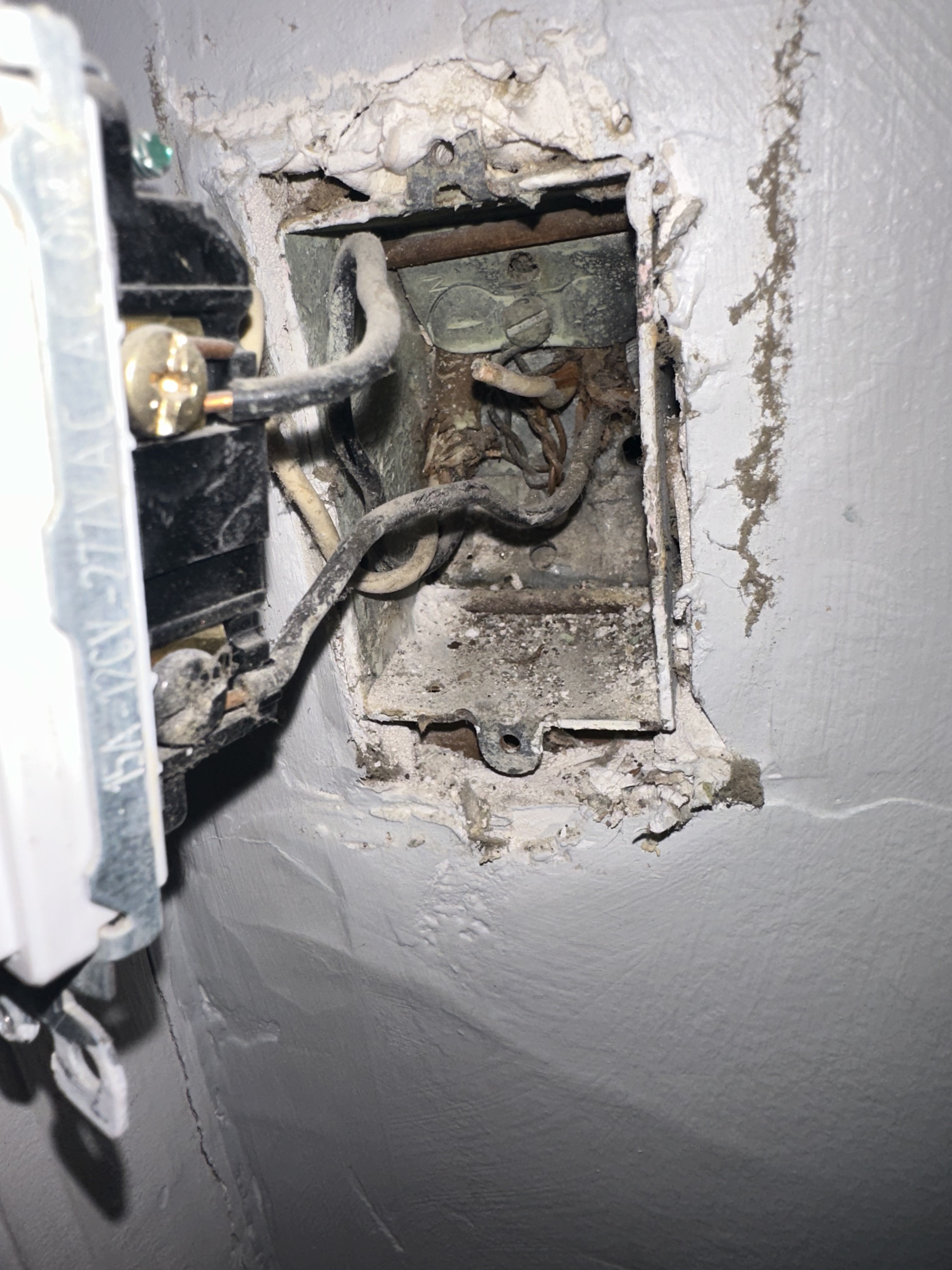
I can’t see that well into the box in the pic you posted, but is there just one 3-wire in there? If that’s the case, that’s not a line in one and load in the other config. It’s also not the line box. Can’t tell for sure without better a better pic with everything pulled out so all conductors and connections are visible.
Report back after you test.
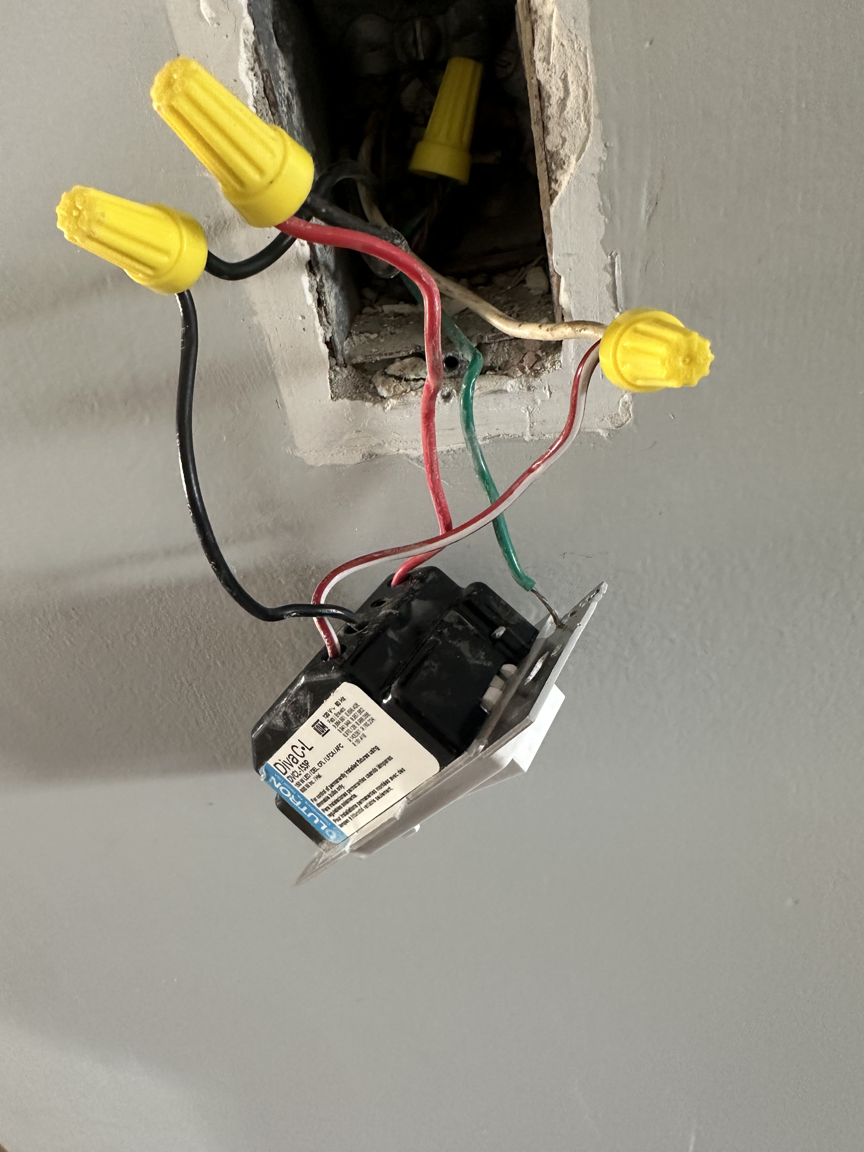
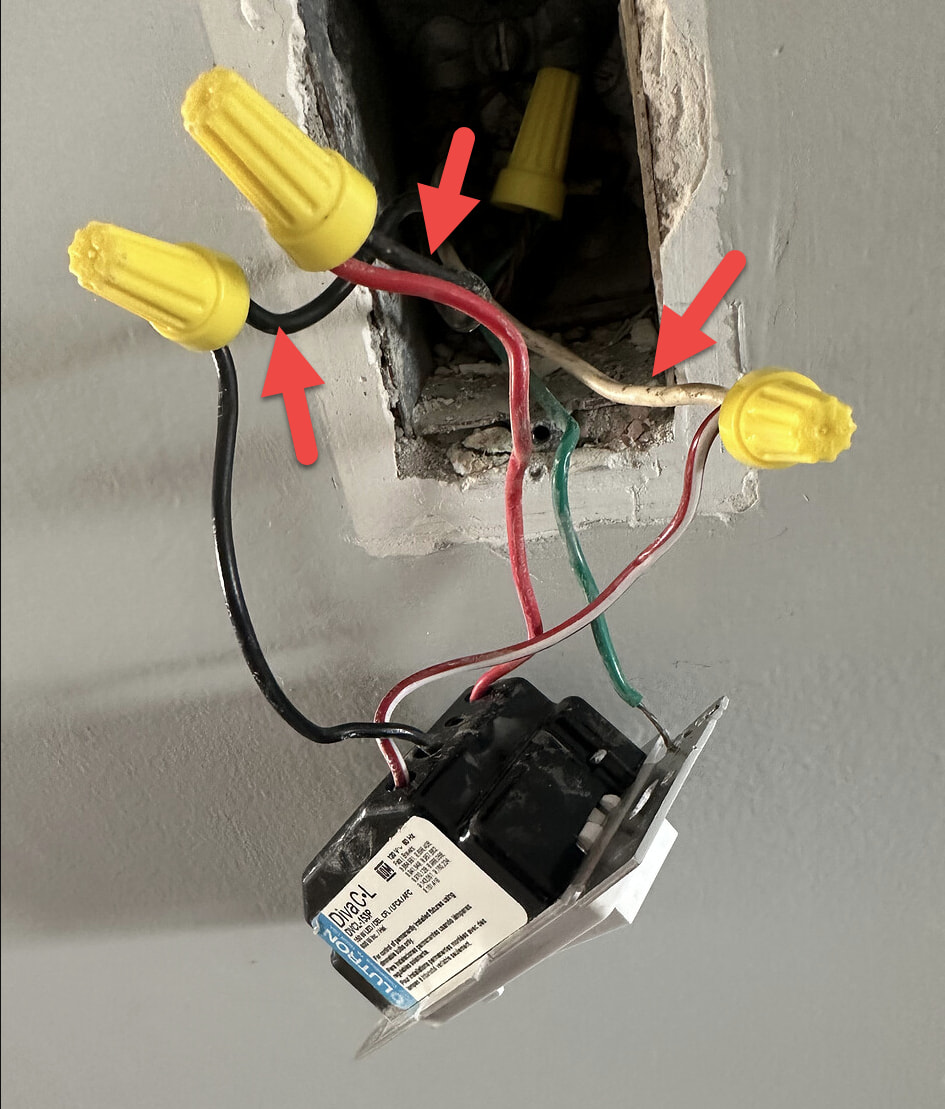
this is before I put the Inovelli in - was using as reference to match wires from the old Lutron box to know where they should go in the Inovelli. If the black wire from the Lutron was the line i put that into the line, the red/white wire from the Lutron was the traveler. I plugged the white wire into the traveler, etc etc
Unfortunately, different brand products wire differently. A Diva dimmer wires completely differently than an Inovelli, so it’s best to evaluate your wiring topology and disregard and current non-Inovelli product wiring.
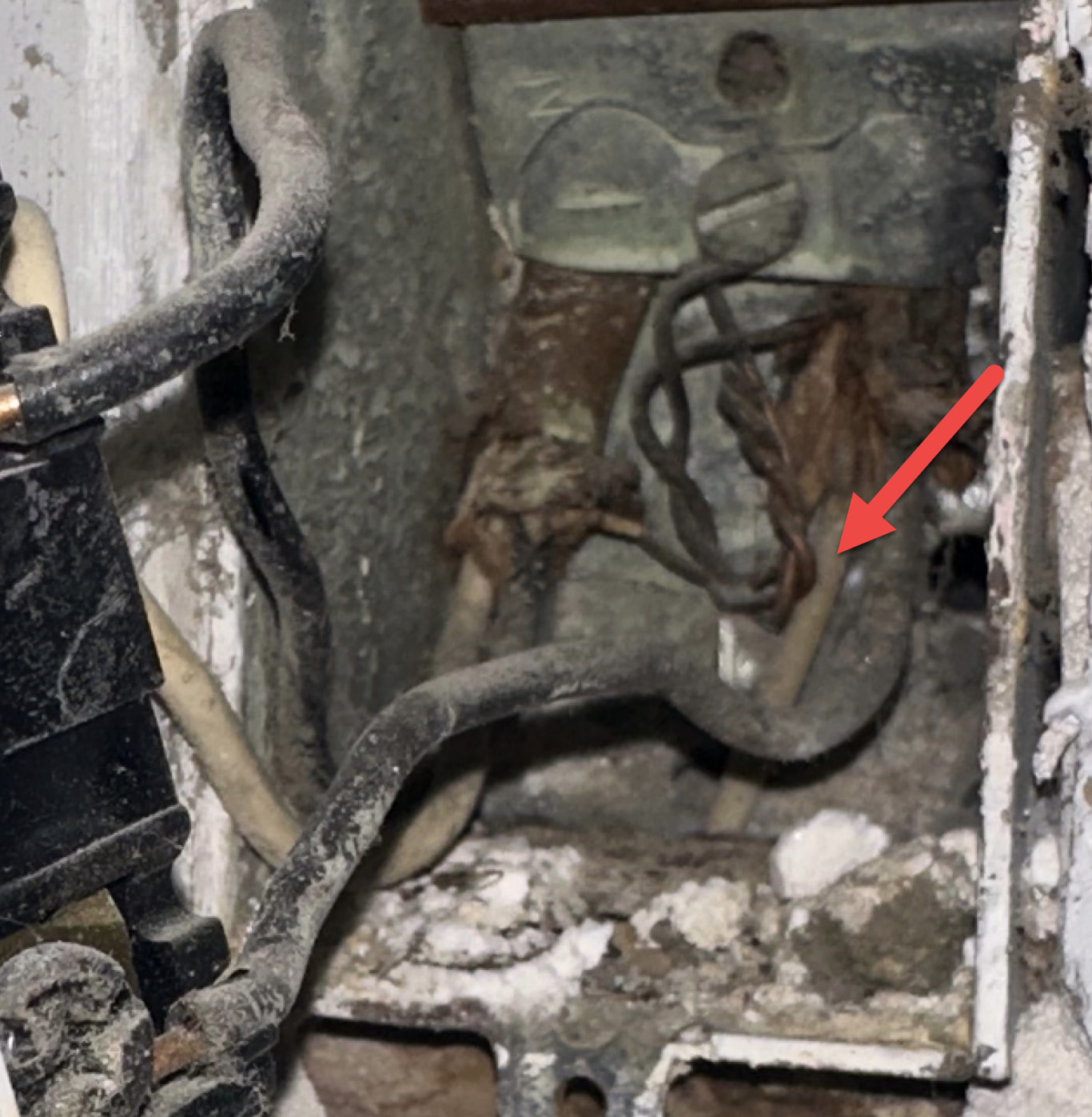
Ok so I removed the switch and here is a picture inside the box 2 black and 2 white. I found which of the wires is always hot - I hooked the black hot wire to the line, I hooked the hot white to the neutral, the black wire that wasn’t hot when tested I connected that to the load and the white I connected to the traveler. And the ground obviously to the ground
Here’s what’s currently happening….
when the dumb switch is off the Inovelli has power, but I can’t turn the lights on at the Inovelli using the paddles.
If I then turn the dumb switch on I’M Able to control the lights at the Inovelli switch using the paddles
the two wires (black and white) on the left hand side are both hot
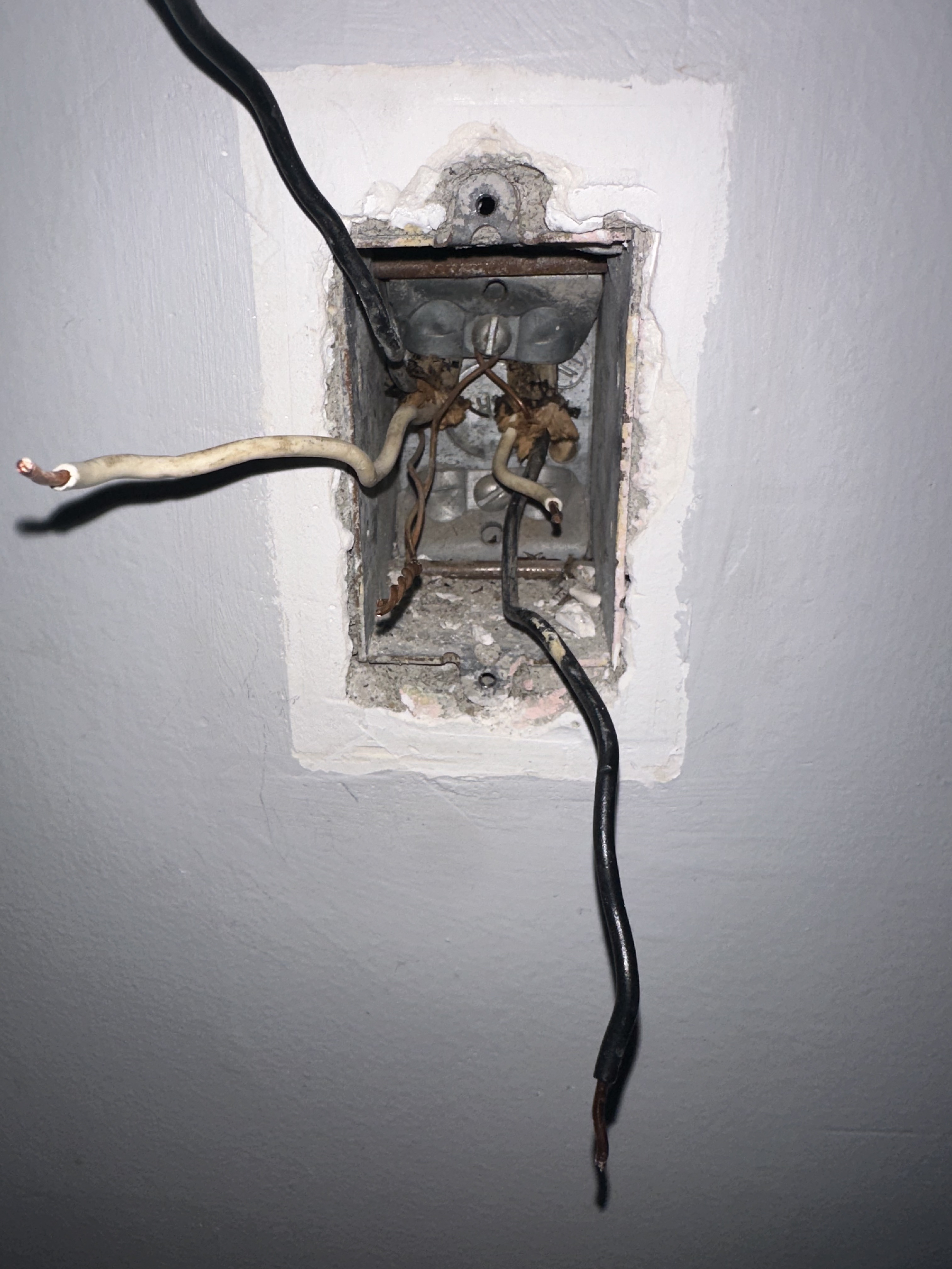
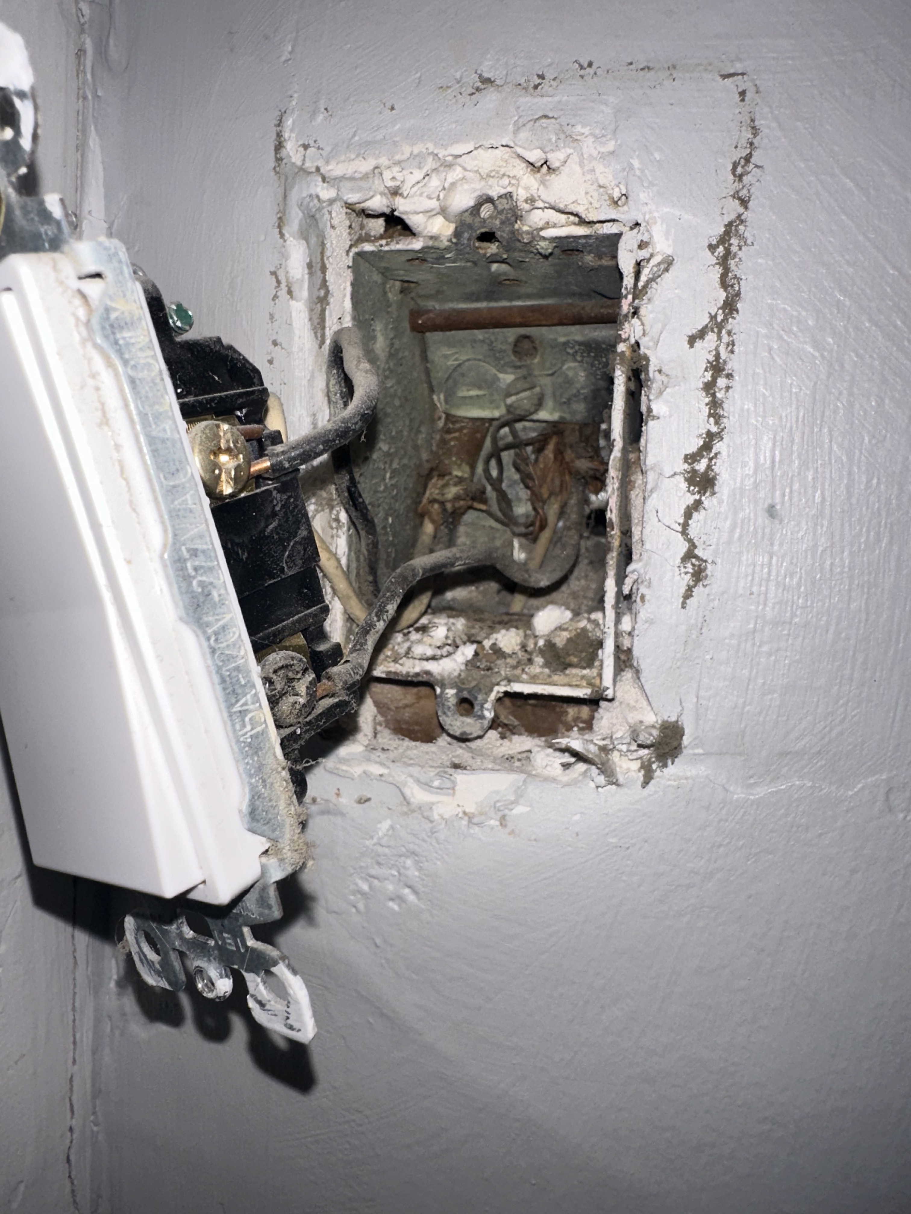
So the last pic you posted with the grey wall . . that is the OTHER box, right? It’s not the same box as in the first picture, correct? This box had the dumb switch? How were those conductors connected?
It’s unusual to have 2 2-wires in a box with a 3-way switch leg. Although sometimes two 2-wires are used instead of a 3-wire.
Do you have a meter? If so, test between the black hot on the left and it’s white. What AC voltage do you get?
Ok, please name the boxes. At this point, neither of us knows where the Inovelli will go, so that’s not a good way to label a box. The two boxes should be named by location.
Do you have a meter? If so, measure between the hot black and it’s white (the pair on the left) in the box with the grey wall.
Ok thanks.
It the location where the Lutron Diva was, there are three conductors connected to the switch. I know there are two 2-wires in that box as well. Three conductors were attached to the switch, 2 blacks and a white. Was the fourth conductor, a white, attached to anything, or was it unattached just like in the other box?
at the box where the lutron was (and where I thought I was putting the inovelli) it was unattached - capped off
Ok, I see what you have. Give me a minute to explain. It’s a bit complicated.
I see your wiring topology and I’ll explain it here. Unfortunately, because of the use of 2-wires instead of a 3-wire, this gets more complicated and may require some tracing.
You have a non-neutral with power to the light box. From the light box, there is the equivalent of a 3-wire to each switch box. I say “equivalent” because instead of using a traditional 3-wire with black, white and red conductors, they used two 2-wires. So in each switch box two blacks and one white are used (hence the 3-wire). This also explains why one white in each box is not used and is not connected to anything.
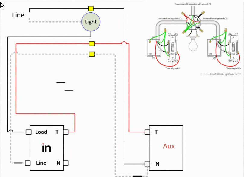
I only know one way to wire this. It requires an Inovelli and an Aux switch. I don’t think it can be done with a dumb switch.
Refer to the drawing below as I describe this. In the top right “before” drawing, you can see how power comes into the light box first. The neutral remains at the light box, hence the non-neutral. You can also see the two 3-wires, one going to each switch box.
To wire this, start at the box with the hot black conductor. The Aux switch goes there with that hot connected to the neutral terminal. Connect another conductor, probably the white that was used before and connect it to the 2nd hole on the Aux’s neutral terminal. (The Aux needs a hot conductor in a non-neutral config, in case you were wondering.) Connect the other black to the traveler terminal.
Now go the the other box. The Inovelli goes there. One of the two whites, probably the one used before, will not be hot (because of the wiring in the Aux box). Connect that white to the Line terminal on the Inovelli.
At this point you have two blacks to connect. One is going to the light and the other is the traveler going to the Aux. I know how I would trace it, but I’m not going to suggest a technique here. Once you have that figured out, connect the black going to the light to the Load terminal and the other black going to the Traveler terminal.
The switch should detect as a non-neutral, or set it that way depending on the firmware level of the switch. Also set it to 3-way momentary, 3-way Aux or however your hub describes it.
This will work so long as the connections in the light box match what is in my drawing.
I know this is a bit complicated, particularly since they used 2-wires instead of 3-wires. That’s not incorrect, it’s just less common.
If this seems too complicated or you feel that you’re in over your head, consult with a licensed electrician. If your eyes have already glazed over, any decent electrician should be able to follow this diagram without an issue.
I’m not going to be able to help much more, but at least now you have a better idea of what you have.