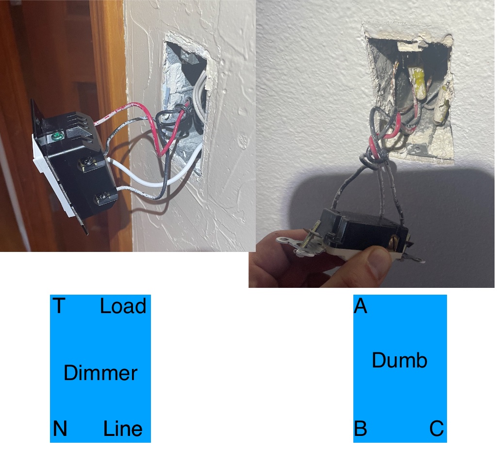
So I just replaced an old analog dimmer (which is attached to about 6 LEDs) with an inovelli switch and I’m having some issues.
As it stands the Dumb switch controls the lights on / off (only) and the inovelli is able to dim them “somewhat” (which makes me think I might need a bypass). I’m using Home Assistant and ZwaveJS to MQTT and use the interface there to change the various settings on the switch to try to get it to function properly.
What I did was try the combos of inovelli on/off and dumb switch on/off and take the voltage at all the different points to see if maybe I wired something wrong or if anybody can offer some help.
When the red dimmer is off → I do see a dimming on the lights but they do not turn off (I assume I need to install a bypass I guess… and/or I should have taken the voltage across the LED lights - but there are 6 of them so this is throwing me off
So if anybody can offer some assistance I’d be real appreciative. I’m not super smart about wiring (obviously) but I’m hoping there is enough info here to make some progress.
Thanks
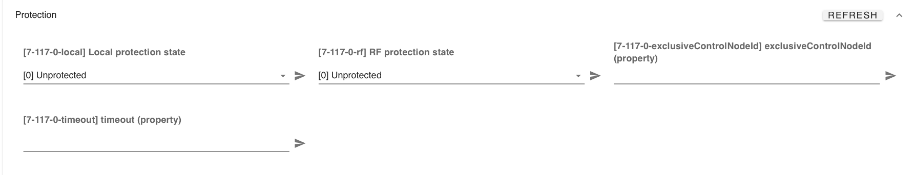
Here is what I currently have set in ZwaveJS/MQTT:
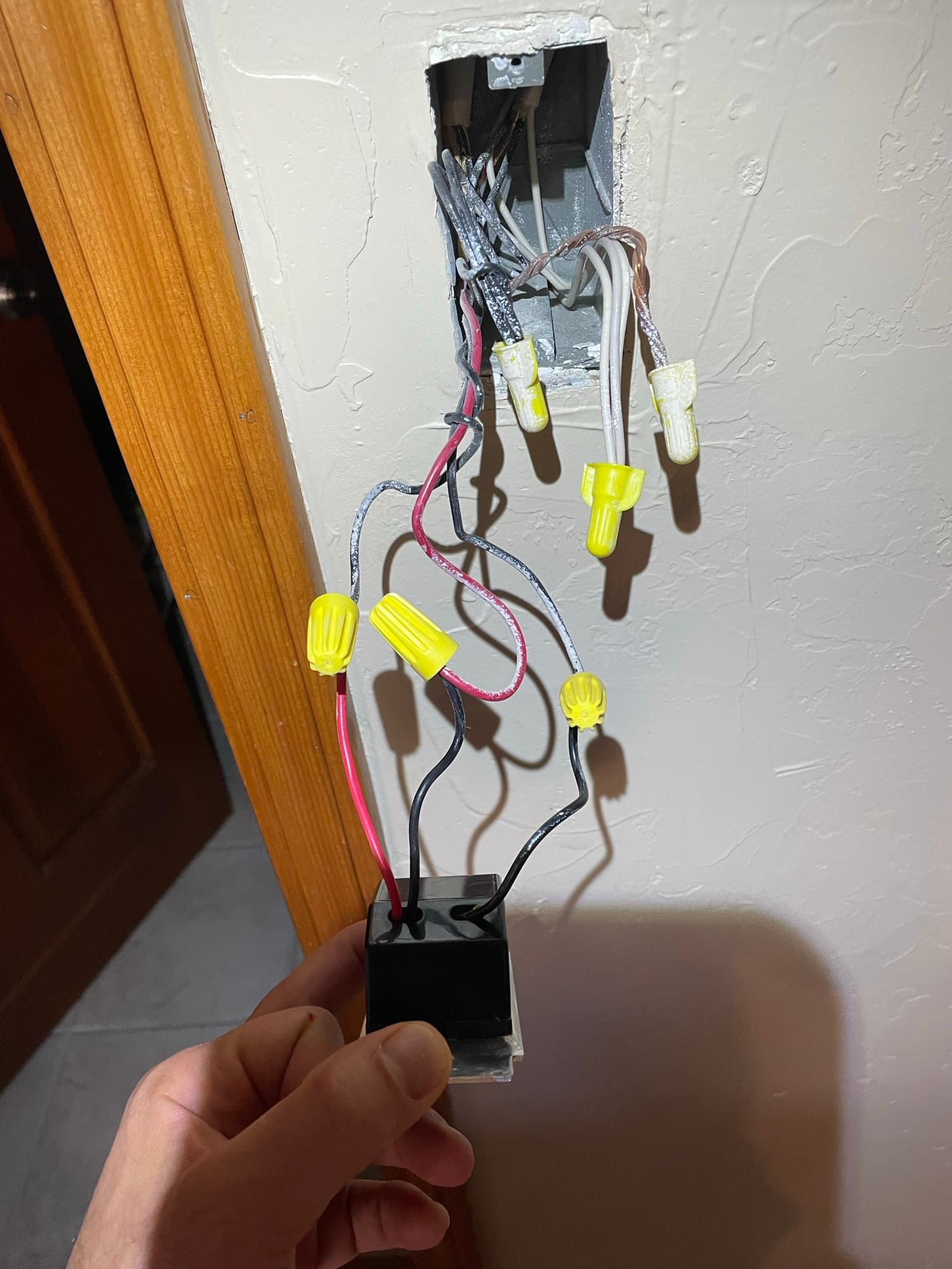
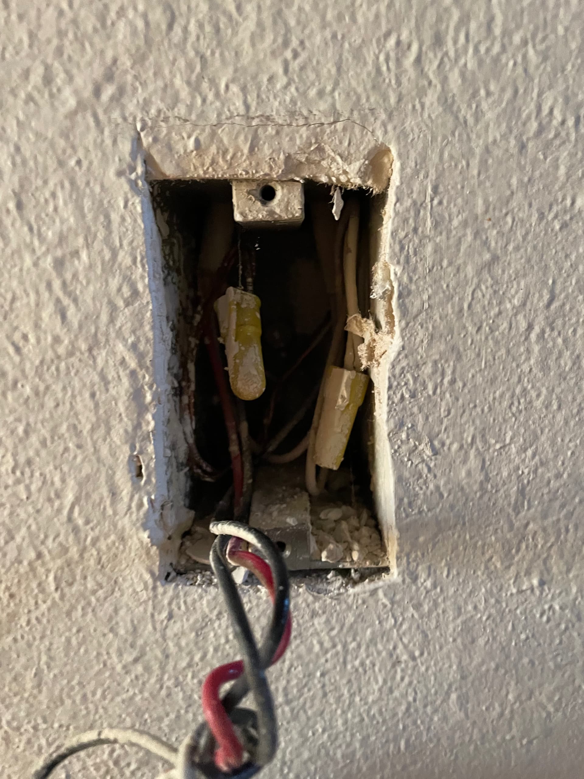
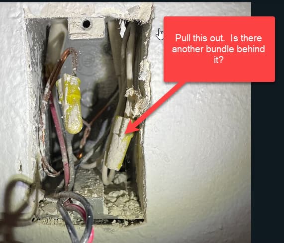
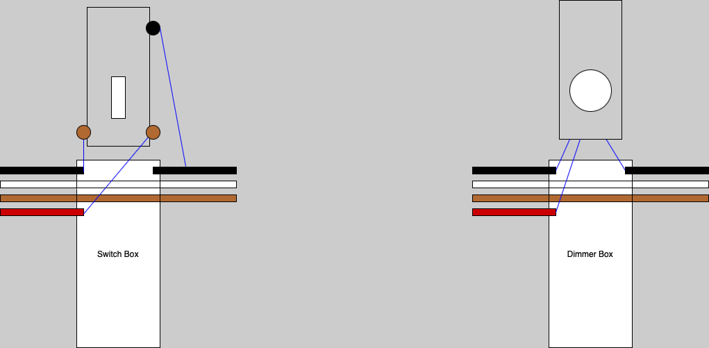
You’re going to have to pull everything out of the box (leave the bundles intact) and then post pictures so that we can see into the box as well. Not only do we want to see the connections to the switches, we want to see the number of cables coming into the boxes.
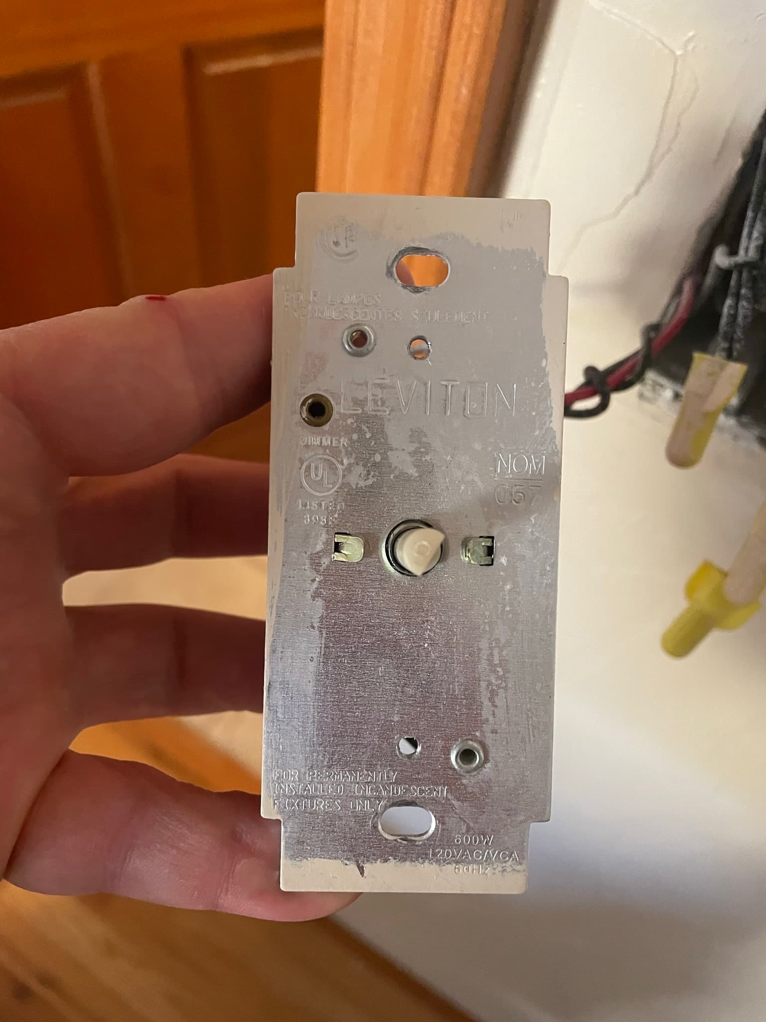
Do you have pictures of how the original dimmer was wired before you replaced it with the Inovelli?
So in the “right” dumb switch box, how many Romexs are coming into the box? I see a 3-wire at the top left, which will be from the other switch. But in the top right, which I can’t see well since they’re not pulled out, it looks like two 2-wire Romexs? Is that correct?
I would ordinarily expect to see one, not two 2-wires. What are these switches controlling? Are there lights in two locations?
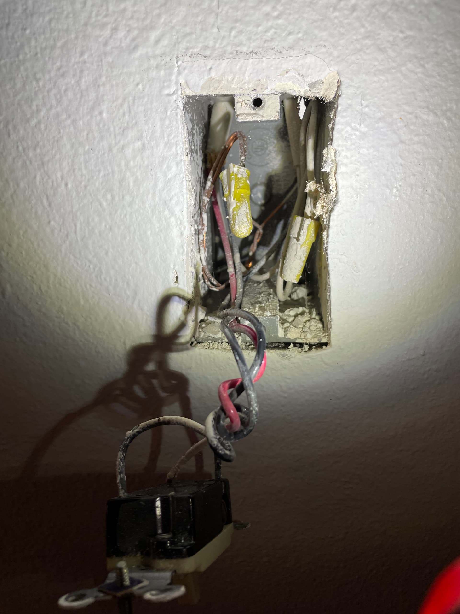
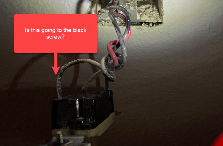
You’re going to have to pull that stuff on the right out. I’m I see the whites bundled on the right, but is there a black bundle behind it. I’m looking to see where the conductor that is connected to the black screw on the switch (which I also can’t see) is going. Is that the black conductor that is wound around the other two?
I mean off hand it looks right. Have you tried configuring the switch locally instead of through HA? Bypass is probably necessary for sure.
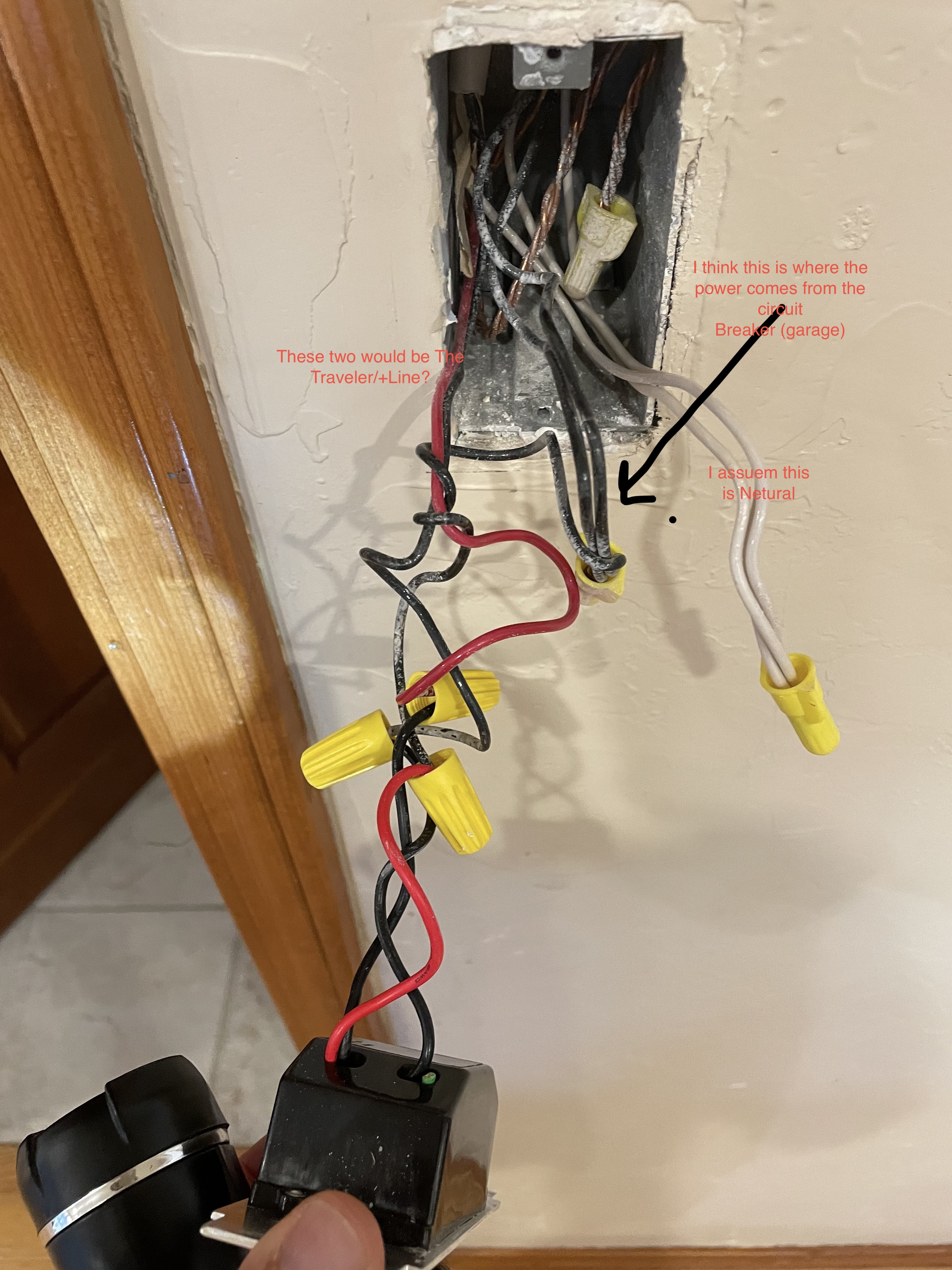
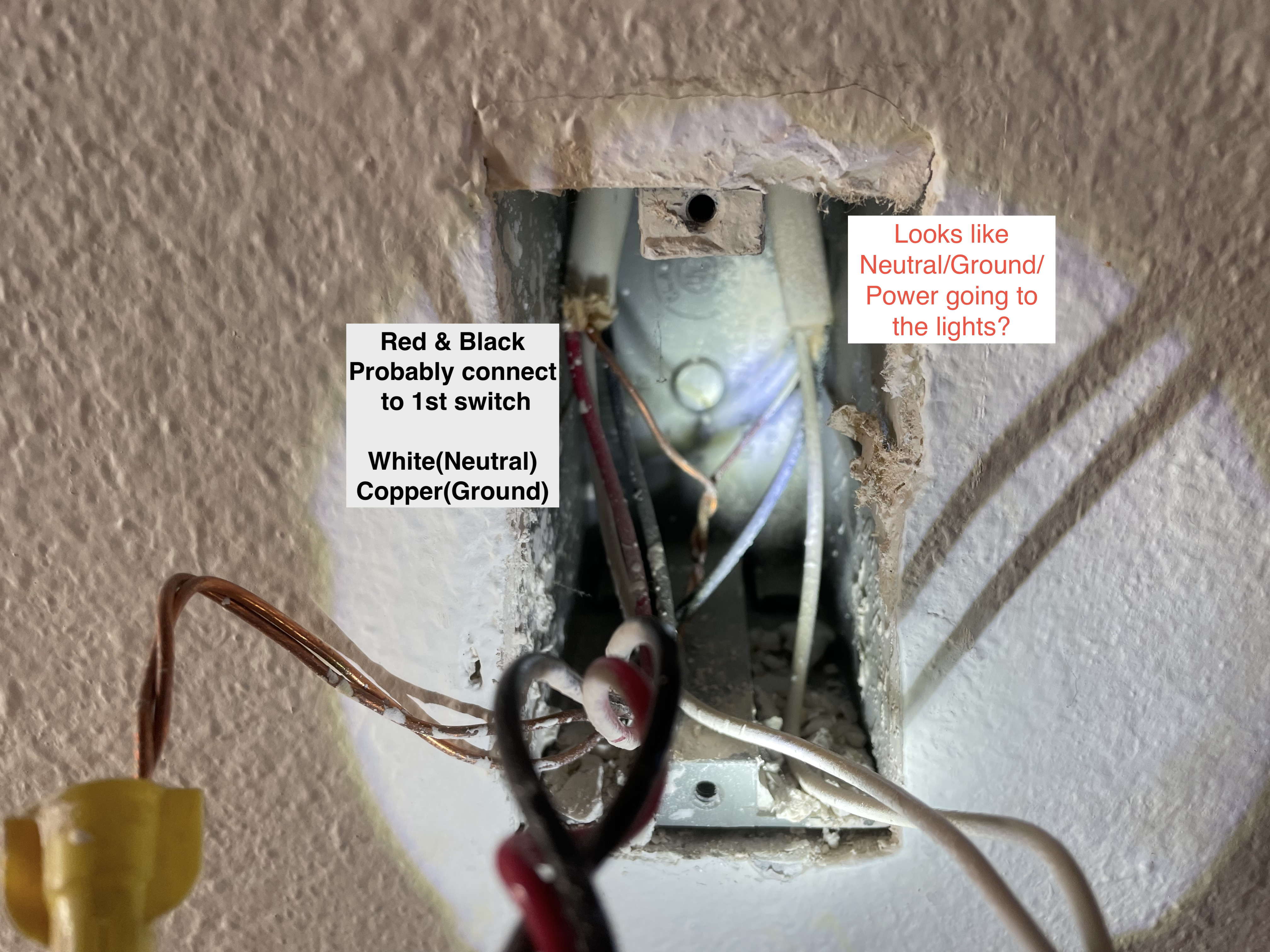
The first box, the BLK line, is it coming out of the same Romex as the WHT neutral bundle you suspect? I see two ROmex. I assume one is going to an outlet.
Some LEDs regardless of wattage will sometimes require a bypass if you notice dim lights from the fixture if the switch is off. Not always but sometimes. Now if I’m reading your sentence correctly you installed incandescent lights in the LED can? Or LEDs retrofit into older incandescent cans?
Looks fine to me too. I thought I saw 2 2-wires in the dumb switch box, but with the extended I see that’s not the case.
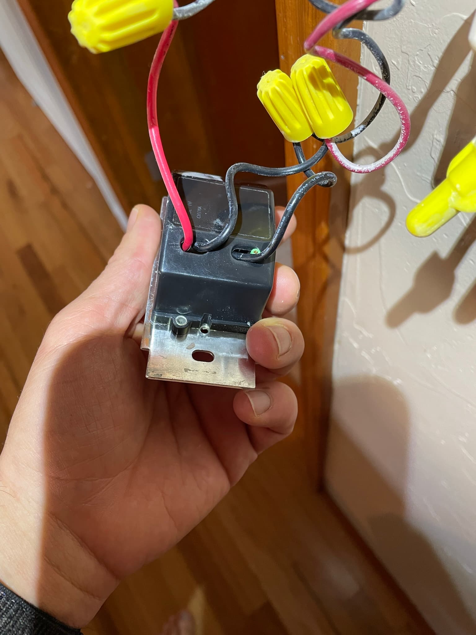
Just to confirm in the Inovelli box, the line and neutral should be coming from the black and white bundles. The load and traveler on the Inovelli should be the black and red on the 3-wire. I think it’s correct, just confirming.
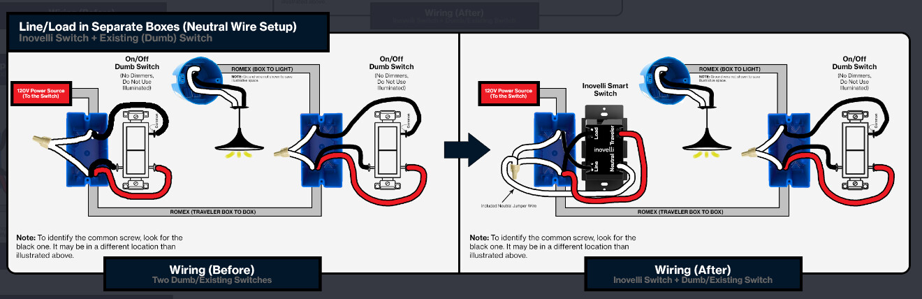
Looks to be a straightforward line/load in separate boxes.
It the picture on the left it looks like the incoming black is jumped to the 2nd box
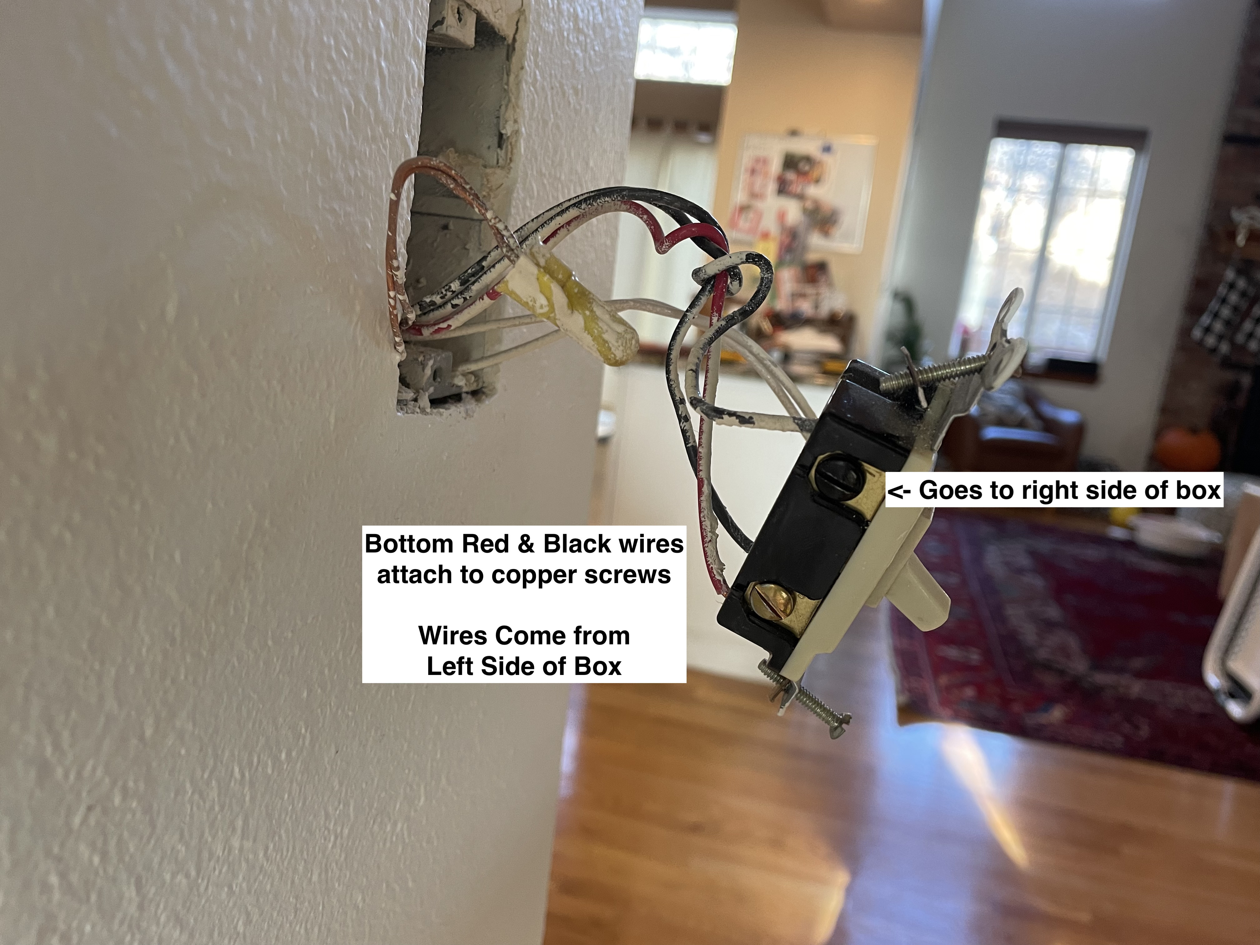
Where as in the picture on the right the incoming black goes into line and isn’t jumped…
Am I reading that correctly? If that’s the case I may need to change how all the wires are spliced together in the existing dimmer box.