Series Dimmer (LZW31), Black
I have a “simple” three way design. The dumb switch only has the traveler wire connected to primary switch. It’s next to basement steps so I could see and trace the wire.
The primary switch has the traveler and then just one other line coming from ceiling light. I just have Black, White and ground.
Thinking my only wiring option is black for line, red traveler, white neutral. But that would mean I do not have a wire to connect to the load.
Anyone heard or seen this before? I wasn’t going to “test” and blow my new Inovelli switch.
Thank you,
Brian
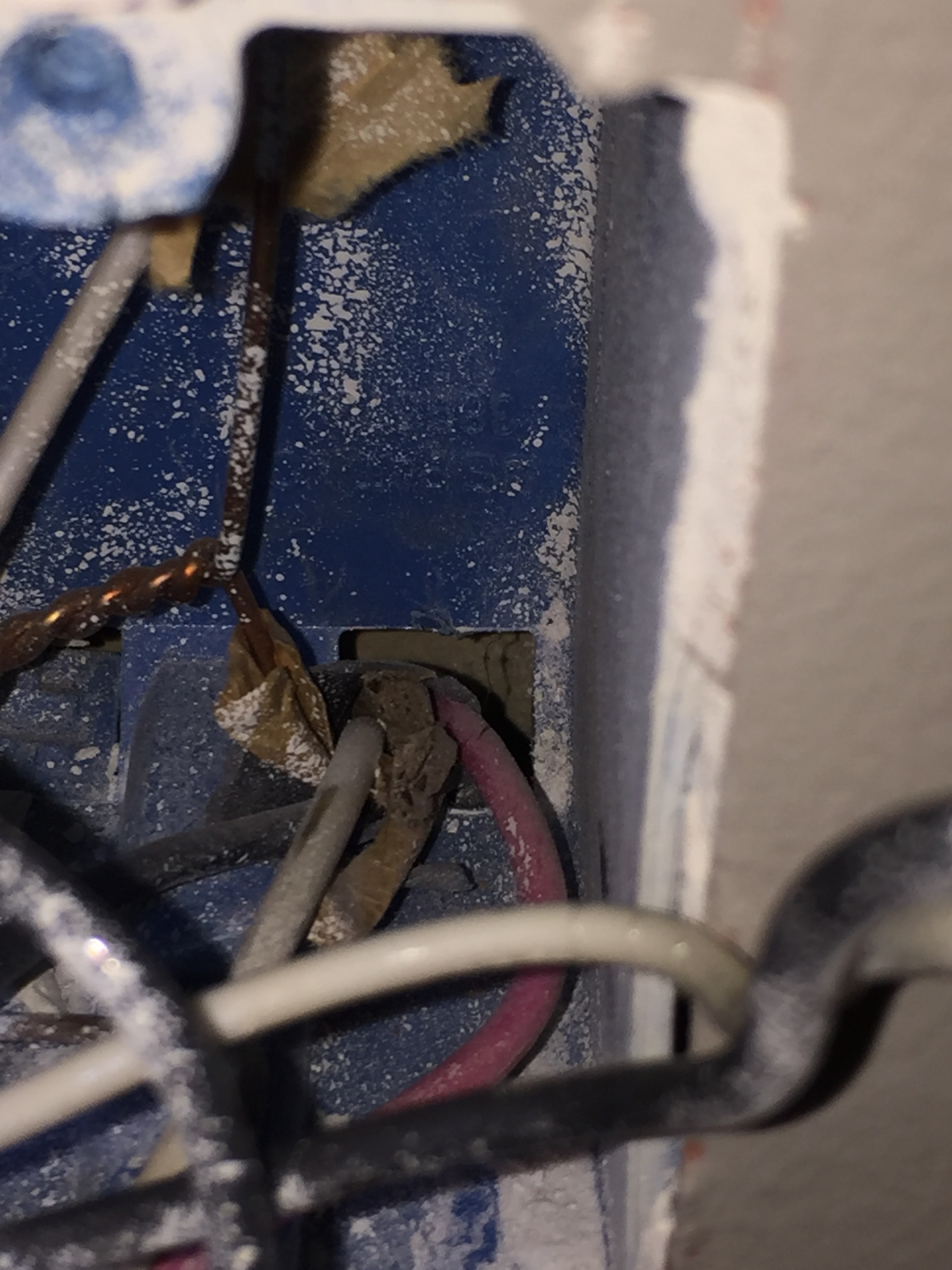
This sounds like you have line from load center going to the light first and then dropping the “hot” down to the switch causing a non-neutral load. Photos will be extremely helpful to provide assistance in your setup.
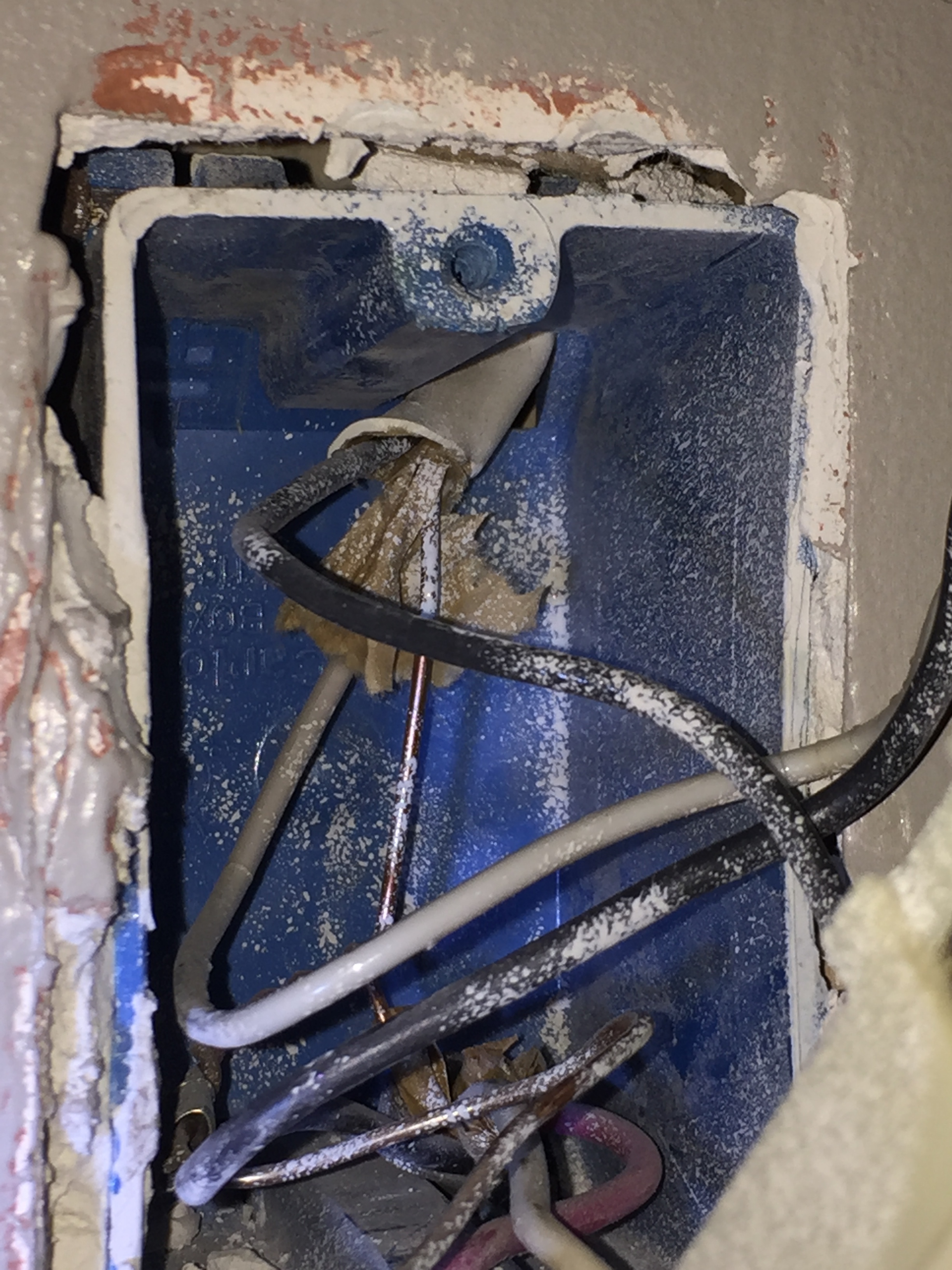
And when you do take the the pictures, pull the switches out so that we can see ALL of the terminals and into the box. If there are other conductors tucked up pull them out as well.
Let’s call the boxes A and B, or top of the steps, bottom of the steps, etc. For now, let’s not put labels on them that suggest their position in the circuit. We all use different terms, so “primary” may mean one thing to me and another to @harjms.

Fortunately you have the dimmer model since this setup is a line/load same box, non/neutral.
The BLK coming from the 2 wire Romex is line. The WHT Romex from the 2 wire is the return that is wire nutted together with the 3 wire Romex is the load.
In box A
Leave alone.
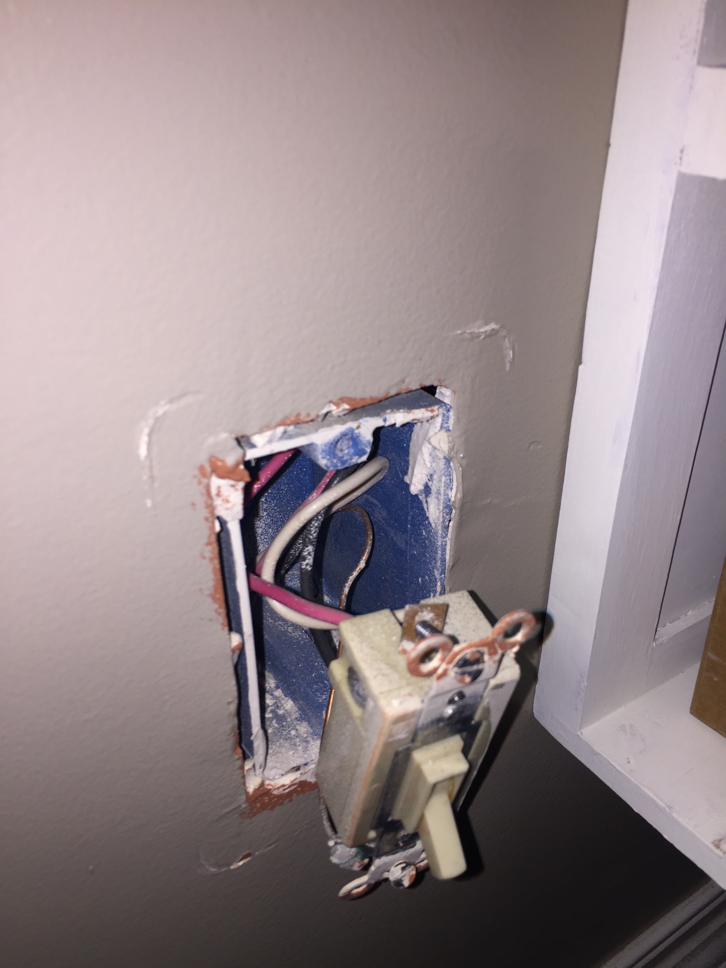
In box B
You’ll need to connect the BLK from the 2 wire Romex to the Line port of the Inovelli. Then connect the WHT from the 3 wire Romex to Load on Inovelli. Connect red to traveler on Inovelli. Restore power. Configure switch for 3 way dumb or toggle and non-neutral.
1 Like
@harjms Are you sure about that???
Most electricians would send the constant hot to the other box where it gets switched back to the first box. So it’s possible (likely, maybe) that the hot is being sent on the white from the light to box B. It’s coming back switched over the travelers and then sent to the light via the black on the 2-wire.
@the5evansfamily Do us a favor and confirm a voltage reading. Do you have a meter? We need to figure out which of the 2 conductors of the 2-wire in box B is hot.
In box B, remove the wire nut connected the white from the 2-wire and the black from the 3-wire. With the wires untwisted, test between the white from the 2-wire and the copper ground. Let us know if there is a constant 120V there. To be thorough, test with the box A switch in both positions.
If you don’t have a constant 120V on the white, put it back as it was before you took it apart. Remove the black from the switch (box B). Do the same test between the disconnected black and the bare ground. See if there is a constant 120V there.
Definitely not. It could be the opposite way, but I’m not sure why most electricians would send it to the furthest box. I’m not an electrician, but just using James’s common sense (may be right, but usually wrong).
@bry - Could be a switched neutral. 
1 Like
Yeah, we don’t want that again.
@the5evansfamily We’re having this discussion because the connections at the light can vary. So doing the test at box B is the easiest way to confirm.
BTW, you’re going to need an Aux switch for box A.
And most likely an Aeotec Bypass to install at the light.
Just a quick update as I have not yet complete the test on the switch B as asked. I took down the light to check it’s wiring. It only has one set of wire that matches what is switch B. The black, white and copper. So the puzzle gets more complex. I will update as soon as I can test line.
Thank you all for the help so far.
No worries.
Like a single Romex only in the light box? Grab a pic while you have it dropped.
We’ll adjust testing after you post back with the initial test.
I knew I should have snapped a pic. But black from light to back in electrical box. White from light to white in electrical box and then copper ground. That’s all that is there and I have changed that light a few years ago. Pretty basic.
Ok, thanks. If that is the case I don’t expect 120V on either the black or white 2-wire in box B but please test anyway. Something in your wiring still makes me think the power is coming from the light. We’ll figure it out.
Is there another light in the path?
There is only one light, and since I didn’t see two settings of wiring when I opened the light outlet as I was hoping their would be it leaves me confused. No idea where power is coming from.
How about a switches outlet? Cuz something isn’t making since. Voltage test will help.
Completed the test and as expected you were right power is coming from the white into box B. So power is coming from the light somehow.
So that being said any ideas for next step? Thank you!
Brian
Sure, so you have a power to the light non-neutral.
So you understand your circuit: Presently, constant hot power is provided to the light first. It is sent to box B via the white 2-wire. In box B, the hot is sent to the far box A via the black of the 3-wire that connects the two boxes. In box A, the black is connected to the common terminal, where it is switched via the travelers, the red and white of the 3-wire. Depending on the position of the switches, the switched hot is returned to the light via the black 2-wire attached to the common terminal of box B.
You’ll use this wiring diagram:
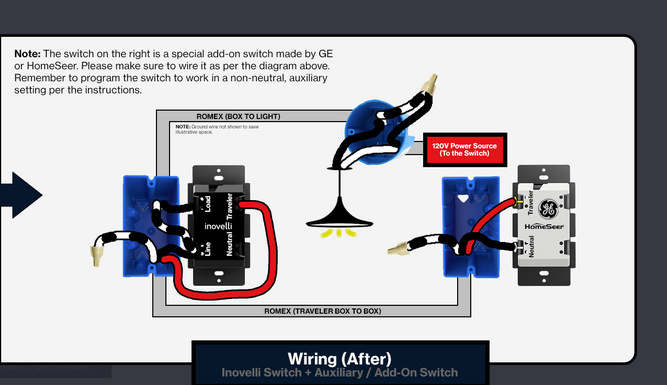
Box B:
Inovelli Dimmer
2-wire: Black to Load, White to Line
3-wire:Wire nut on the white; it’s not used. Black to Line, Red to Traveler
Box A:
Aux switch (GE Enbrighten Add-On #12723, #46199 or HomeSeer Add-On #HS-WA100+)
Wire nut on the white; it’s not used. Black to Neutral, Red to Traveler
Switch parameters:
21: 0 - No neutral
22: 2 - Multi-switch (Aux)

Black dimmer manual:
1 Like