I am new to the Innovelli ecosystem and wiring up my fist switches. I’m trying to replace a 3-way dimmer switch with a smart dimmer and an aux switch, but am stuck on the wiring.
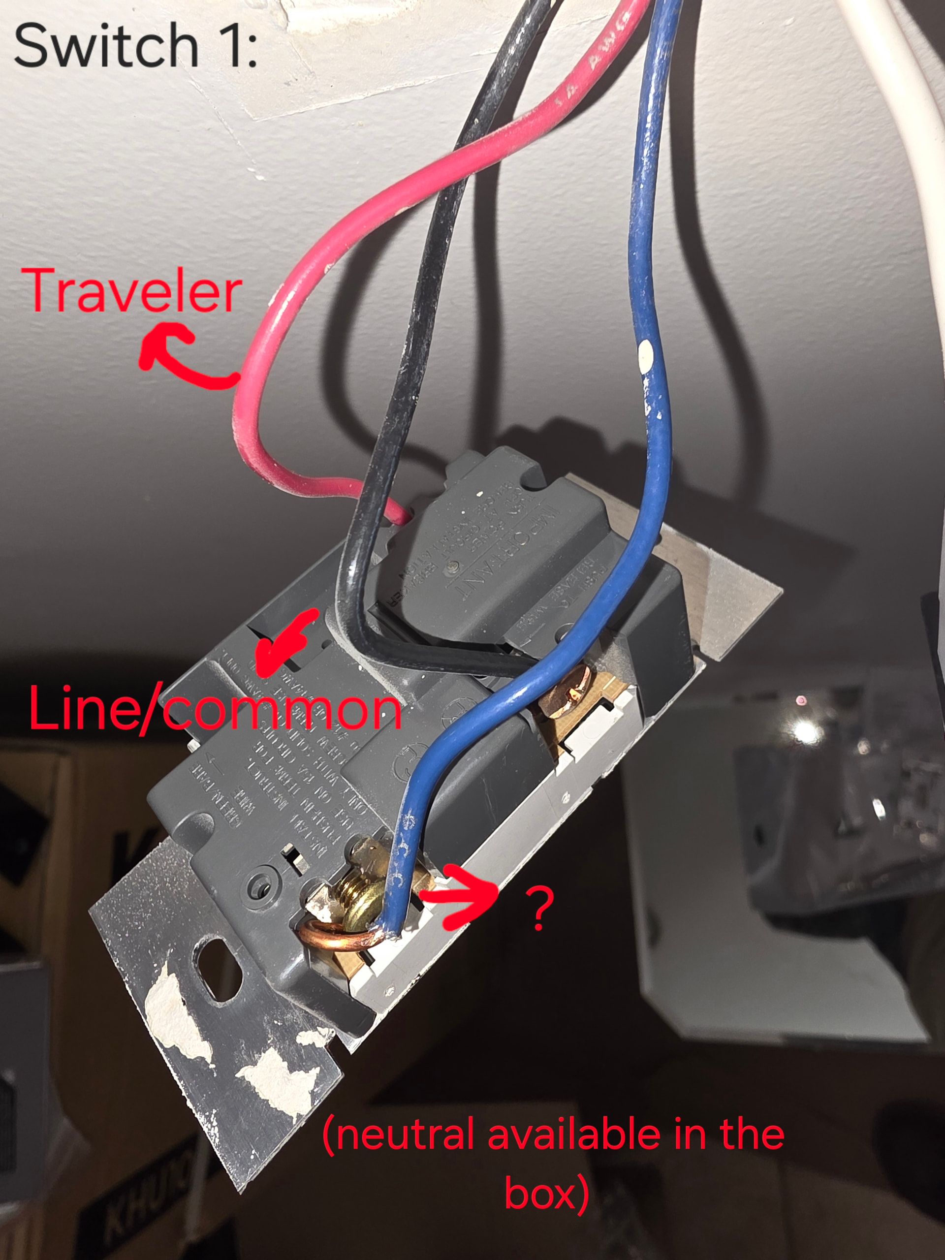
It seems I have line and load in separate boxes - but I also have a random blue wire that I have no idea what it does (doesn’t seem to be a traveler). I also have what seems to be the neutral wire already plugged into one of the dumb switches. I’ve attached photos of the two current (dumb) switches; switch 1 is the dimmer and switch 2 is the dumb on/off switch controlling the same lights.
Im not sure what to plug in and where on the Innovelli switches - any advice would be much appreciated. Apologies for the noob question.
In a 3-way switch circuit, you will have one “common” wire and two travelers.
You will need to verify which wire is your Line wire with full time 120v and which wire is your Load wire going to your light. We can then determine which wires need to be repurposed to carry either power or neutral for the Aux switch.
Can you provide a couple extra photos of the wiring where it enters the box?
I’m no longer there to take more pics, but I verified that the black wire feeding Switch 1 is the line (it remains hot when switch is off). So I assume the other two must be travelers. There is, separately, a neutral wire that is capped off in the box.
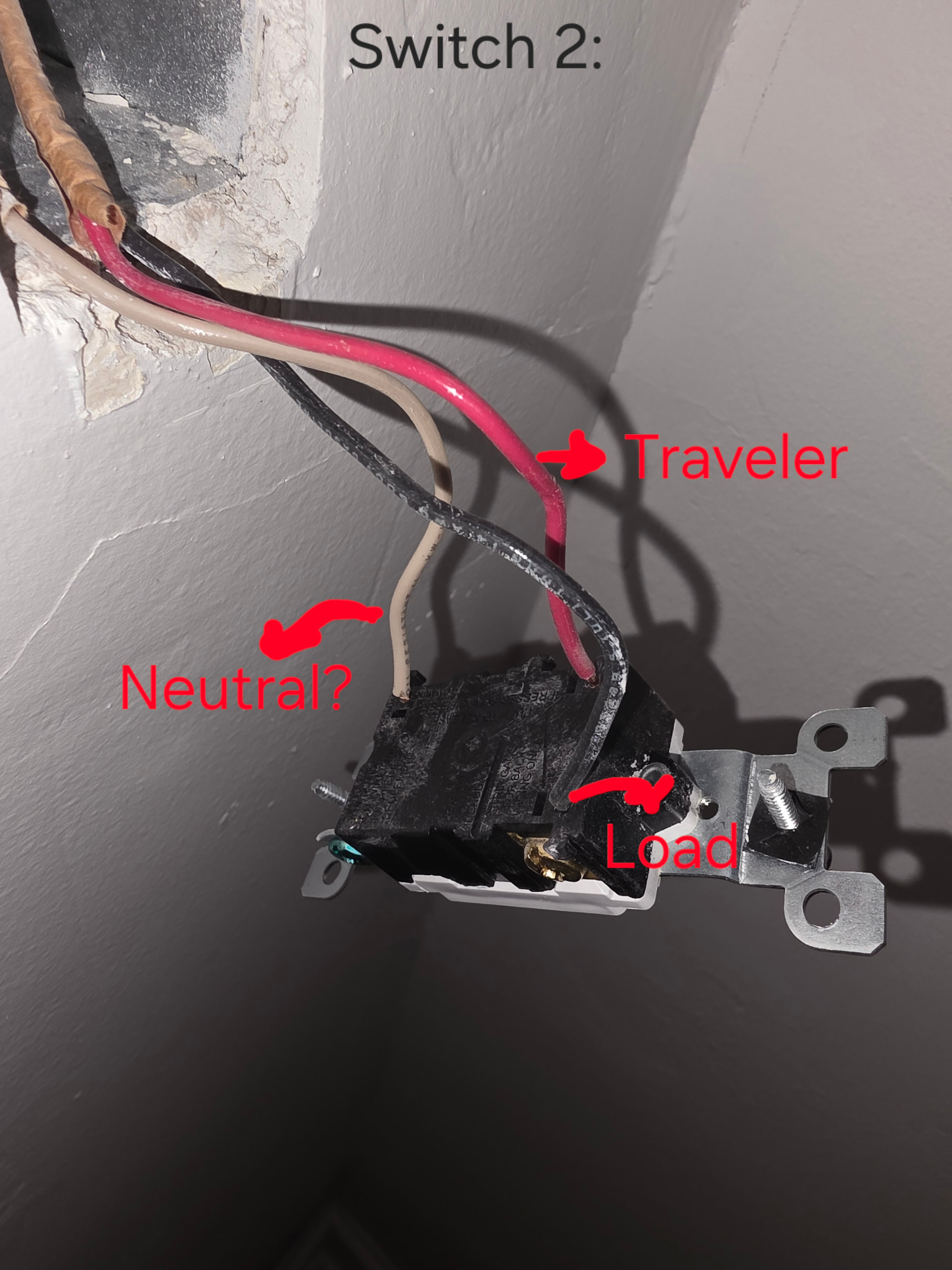
For switch 2, I am not sure how to verify which wire is which. The white wire is attached to the black screw on the switch - maybe that means it is load? There are no other wires in the box (no capped-off neutral wires) and all three wires enter the box together.
If the white wire is connected to the black screw on Switch 2, that would be the “common”, and can either be the Line or the Load… the black and red wires on BOTH switches will be your travelers between the switches… meaning that the blue wire is your Load if it isn’t hot all the time.
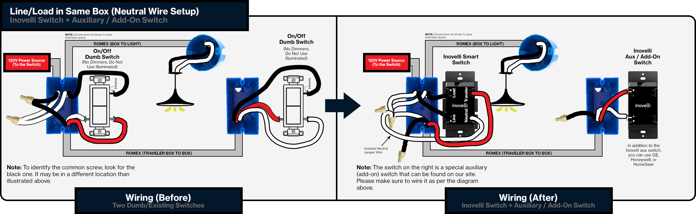
This is essentially what you have with different wire colors:
So, in the box with Switch 1, you will need to find the wire that the white wire from the 3 wire cable is connected to… that other wire, likely black in color, will be your Line and will need to be connected to the Dimmer as such.
You will need to repurpose the white wire from the 3 wire cable as a Neutral for your Aux switch, and connect it to the Neutral terminal on the dimmer along with the actual neutral.
The red wire from the 3 wire cable will now be your only Traveler between the Dimmer and the Aux switch, and you will end up putting a wire nut on the black wire at each end as it will not be used.
Finally, the blue wire will be your Load going to your light, and will be connected to the Load terminal on the Dimmer.
Let me know if you have any questions on any of this, and I can try to help further.
I am going to hazard a guess and say that you are using a non contact voltage tester, correct?
The problem with a NCVT is that it can pick up “ghost” voltage even if the wire isn’t necessarily live, and is only has an induced voltage from wires it is running along side of.
Without further photos and testing with an actual multimeter, I still believe that the blue is your Load wire, and your Line wire is connected to the white wire going to Switch 2.
.
Here is what we know for certain… at Switch 2, the white wire is connected to the black screw, and is therefore a “common” wire. This tells us that both the black and the red wires are travelers. Assuming that the 3 wire cable goes directly from the Switch 1 box to the Switch 2 box (can’t tell without further testing and/or photos), this means that the black and red wires connected to Switch 1 are also travelers.
From this, either the white wire at Switch 2 or the blue wire at Switch 1 should always be hot. Again, you need to use an actual multimeter and measure voltage to either neutral or ground. As you don’t have a neutral at Switch 2 (that white IS NOT a neutral), you would measure each of the insulated wires to ground to determine what voltage it is carrying.
If you do not have a multimeter, and aren’t willing to borrow/purchase one, another thing you can do is remove all the wires from both of the switches… this will leave only ONE wire live, as the others will be either travelers or the Load wire.
You nailed it - I was using an NCVT. With a multimeter, it shows just ~48A on both the blue wire on switch 1 and the black wire on switch 2 when the light is on. Everything else is accurate to how I described it earlier.
Yes, Switch 1 is a dimmer. It’s in a 2-gang box next to another Innovelli smart dimmer (that one isn’t a 3-way, and it was straightforward to get set up. No issues.)
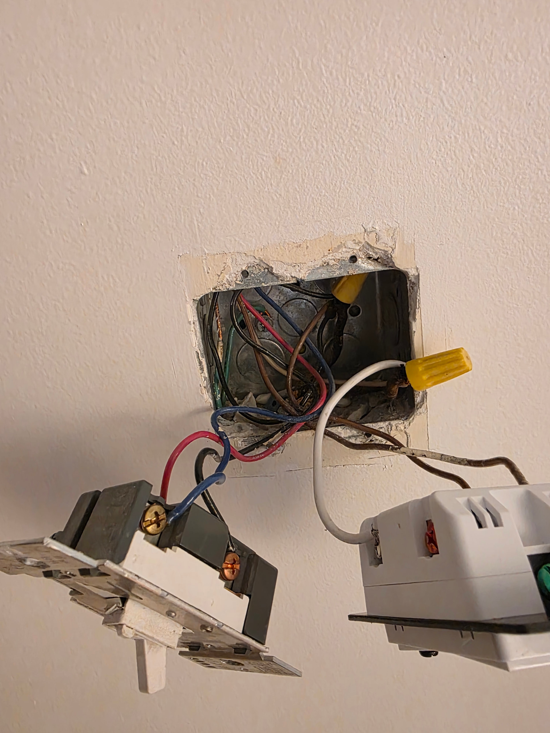
After turning off power to that circuit, completely disconnect any wires connected to Switch 1 and Switch 2. Let’s completely remove the switches out of the equation. We know where everything connects so it won’t be an issue when it gets disconnected.
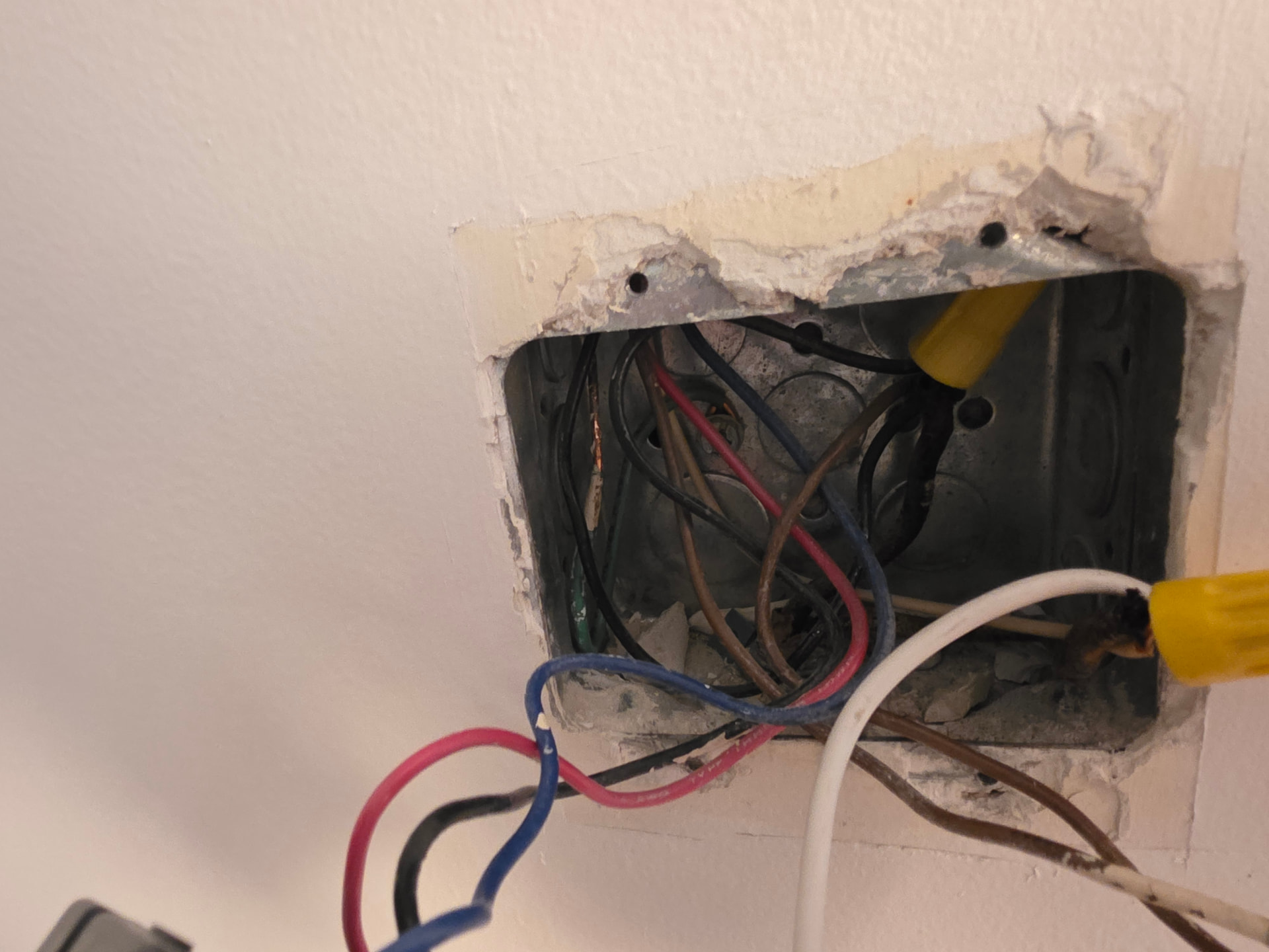
Get another photo of the wiring in box at Switch 1, including anything that may be attached to any of wires in the 3 wire cable going to Switch 2, even if it wasn’t connected to Switch 1.
From here, we will determine which of the wires we need to test for voltage. If the other switch in the 2 gang box is on the same circuit, likely the wire we will be looking for may be connected to the same power wire as the other switch.
Given this new information, and with the new photos, your wiring does not directly go from this box to the box for Switch 2…
As the black is indeed connected to the same hot as the other switch, this means that the blue and red are the travelers, but at Switch 2, the travelers are black and red, with a white common wire.
To make sure you will have a neutral available in Switch 2, you will need to find out where these wires go before proceeding. That white common wire on Switch 2 would be your Load wire and somehow needs to be brought into the box for Switch 1, meaning that changes will need to be made wherever the wires for both boxes meet up.
There is no “simple” solution unless you plan on retaining the “dumb” switch in the Switch 2 location.