Help with Craftmade TMPH44W5

Hi all. I just got my Fan/Light switch (LZW36) and am excited to set it up and add it to HomeAssistant but I’m having a little trouble with the wiring. My fan does not have a similar controller box, which would make a simple replacement.

Here are pictures:

I will try to explain the wiring as best I can:

There are four places the wires lead to, an arc shaped box which I assume is the controller, a small rectangular box (closest to arc), a large rectangular box, and a bundle of cables at the center that go into the fan/light.

There are thick Black and White wires that connect to the wires going the to the wall switch. These come in to a connector clip (as seen in the second picture) which then lead into the arc. In total from the connector to the arc are the aforementioned thick white and black wires along with red, orange, brown and yellow.

Going from arc to the smaller rectangular box (closest to arc) are red and white wires. There are no other wires leading out from the the small box

Going from the arc to the larger rectangular box (further from arc) are red, black and grey wires. There are no other wires leading out from the the larger box

Going from the arc to the center bundle (bypassing the connector clip) are:

  • a thick blue wire labeled, “For Light” which connects to the thick red wire in the center bundle
  • a thick white wire labeled, “AC In N” which connects to a thick black wire in the center bundle

Going from the connector clip to the center bundle are yellow, red, pink and gray wires.

In total the center bundle has a thick red wire (which connect to thick blue wire labeled, “For Light”), a thick black wire (white wire labeled, “AC In N”), and a thinner red, yellow, pink, and grey wires.

My guess is that the arc and the two rectangular boxes are the remote components and I could cut them out, and connect directly to the bundle of wires in the center. My confusion is that the center bundle has six wires and the LZW36 remote has four wires. Any help figuring out how to make this work would be appreciated. TIA

Go to my posting LZW36 Fan wiring

I have different fixture with same wiring. jtronius’s response is, i believe spot on. He put in instructions plus a youtube video of someone else doing it

I could still use some help with this, if anyone is knowledgeable. From mgreenb561 post I understand I may need a capacitor, but I am still confused how to map the six wires coming out of my fan/light to the four wires in the LZW36 controller.

Hey @jtronicus, I heard you are good with these kind of things. Do you have any input that could help?

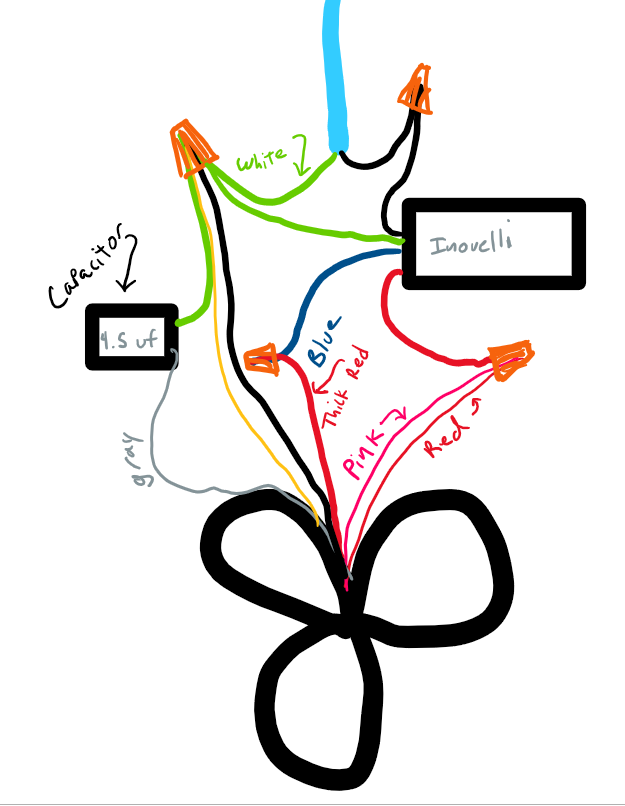
If we just look at the wires coming from the fan motor housing, there appear to be 6 wires:

  • Thick black
  • Thick red
  • red
  • pink
  • yellow
  • gray

2 of the wires are already labeled for us: Thick Black (Neutral), and Thick Red (Light). That leaves us with the 4 wires needed to control the fan and fan direction.

I couldnt find any specific wiring diagrams for your fan, but since the colors match what I found earlier on this post, my best guess is that the wiring would be the same (for downward blowing fan):

This is just an educated guess though. I have not wired any fans this way, and this is based purely on internet research.

1 Like

Thank you! That helps a lot, and I’ll give it a try.

Do you know how I decide what size capacitor?

Generally, you want a capacitor that matches existing one. The sticker (circled below) on the controller makes me think yours is a 4.5 uf capacitor.

Those 2 black boxes are likely your existing capacitors. The one with 3 wires is usually the one that controls the fan speed (you wont need this one because the Inovelli canopy module has its own). The one with 2 wires is usually the motor start capacitor (which you will need or the fan will not start or may spin in the wrong direction).

If the capacitor in the photo with only 2 wires says 4.5 uf, that would be my guess as the correct one.

1 Like

Thank you, I’ll have to take a closer look. Is there any reason I couldn’t use the existing capacitor?

There should be no problem with using the existing ones, other than the fact that you have to cut wires, which could make reverting your changes more difficult if you decide to go back.

2 Likes

Thank you! Your responses are very helpful. My plan is to use the existing capacitor and in the worst case scenario I’ll replace it.

I installed it using @jtronicus wiring instructions (using capacitor that came with fan) and it worked flawlessly on the first try. Thank you @jtronicus!

FYI your color codes seem to be the same as mine. I thought i had a 4.5ufd start capacitor laying around but couldn’t find it so i bought a new one on ebay. https://www.ebay.com/itm/CBB61-Ceiling-Fan-Motor-Capacitor-3uf-4-4-5-6-10-15uf-250V-AC-50-60Hz-2-Wires/183933436015?ssPageName=STRK%3AMEBIDX%3AIT&var=691628440696&_trksid=p2057872.m2749.l2649 I chose not to use the one in my controller because if this does not work, I want to go back and re-wire back in old controller and not have it bastardized. For same reason, i was careful to cut wires on junction side furthest from old controller in middle of wire (didn’t take pic) so i could reconnect if necessary

I wired it as directed from the link from @jtronicus. The good news is i got some response of different fan speeds and light brightness so I think this is do-able. The bad news; after installing device drivers the fan/light is unresponsive (the switch and ST app seem to be communicating LZW36 Fan + Light SmartThings Device Handler Update [07/17/2020]
Waiting for a response to that link and will keep you posted, but as stated i think it is do-able. I’m thinking prob is communicating with module… waiting f/ response from @EricM_Inovelli or someone above my pay grade

@mgreenb561 So the Z-wave side seems to work as you are getting responses from the LED bars, but the fan does not seem to be responding now that the device is included into the network right?

If you pull the air gap on the switch and push it back on can you get the fan to respond for a certain amount of time?

@EricM_Inovelli Nothing It flashes quick Red Green Blue

Sorry, I saw this in your other post:

So it seemed like when you made changes in the app the LED indicators reflected the change.

@EricM_Inovelli Yes. pretty responsive on the app (the led indicators seem to have a lag on the paddles though). No response on fan after pulling air gap

There are 3 devices on app. I found it unusual though that all defaults were missing in ide. I put in parameter defaults 1-30

I can take it down and bench test for module output but I’m pretty sure there is nothing.

Suggestions?

@jtronicus, I just realized that the fan is going the reverse direction. I’m guessing the fix is a matter of switching two wires but I’m not sure which .

I think swapping the pink and yellow wires will change the direction.

1 Like

Do you have the ability to do a firmware update?