I am looking for a Z-wave, Decora-style switch that gets its power from domestic AC but doesn’t require a neutral wire. It sounds like the red series Inovelli devices could fit the bill.
But the LIFX bulbs and plug-in modules I want to control are not on a switched lighting circuit; I simply want the Inovelli device for its ability to join a Z-wave mesh and remotely control other devices via my Abode gateway. Therefore I would install into a wall box location primarily so that the switch has power.
I don’t know a ton about abode but if they support scene control, you’d easily be able to do this with the red series switch using scene control.
Maybe their is another community member that has used abode who has a better answer for you on whether or not it works. It is on our list of hubs to get certified with but we are not there yet.
@anon14959390 Unless I’m misunderstanding what the OP is asking, I think he wants to know if he can install a Red series switch in a box without a neutral and with no load. He wants to use the switch to control lights on an unswitched circuit.
Hub issues aside, my guess is this won’t work as my understanding of non-neutral switches is that they gain a path to a neutral via the load.
I missed that part. I’ll defer to @EricM_Inovelli for that then. I don’t see why it wouldn’t work to control a scene but I’m curious what he would be using to control the load of the switch.
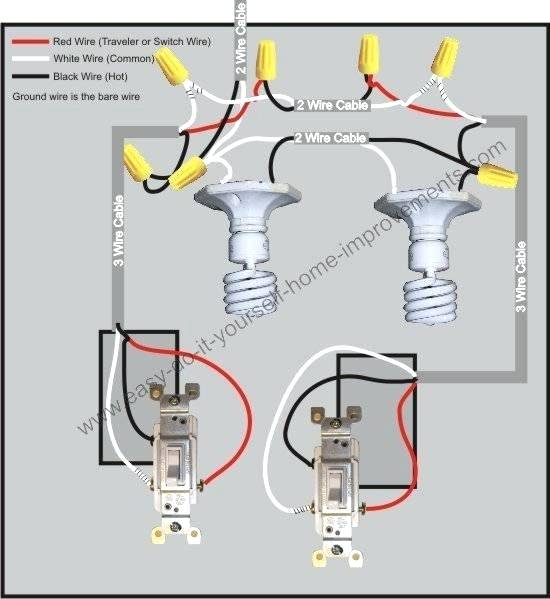
I think Bry has correctly described the situation: using the Inovelli device for controlling lights unrelated to whatever circuit the switch is part of. In fact, I’m not convinced there is any load for a switch to control. The wiring has been sitting behind a blank wall plate cover, probably for 20+ years, and looks like just a wire nut used to splice together hots.
The only purpose of connecting the Inovelli device to AC power is so that the device can participate in a Z-wave mesh.
Edit: there are 3 wires connected by a wire nut, two black and one white. There is also an exposed copper wire which I take to be the ground. All 4 wires are old-school solid core copper, not flexible stranded copper like you see in homes built since about the Johnson Administration.
The box is a dual-gang, and on the “working” side is a dimmer (part of a 3-way overhead lighting circuit whose other switch is about 10 feet away). So maybe this is why the picture shows two black (hot?) wires and one white (neutral?).
Using a multimeter I measured ~122V difference between the theoretic grounding wire and the collection of wires spliced inside the nut. I haven’t yet taken apart the nut to compare voltages across the 3 different solid coppers, but I think it’s fair to assume I have standard 120V residential power to make use of.
My admittedly limited electrical knowledge, I’m the sales guy after all, tells me the two blacks are line and load and white is neutral. I’d be curious what that line would control though. Probably an outlet would be my guess.
Time to do some digging.
Of course there are people here who will know way more than me too so hopefully one of them chime in too. ha ha.
Speaking conceptually- any electrical device needs two wires to form a circuit. Power flows in on one (hot) and out on the other (neutral). The power flowing through the thing is what makes it work- supplying power isn’t enough if it doesn’t have somewhere to flow to.
To make a sink analogy, hot wire is the tap plumbing, and neutral wire is the drain. All the neutrals in your house are connected together in your electrical panel (as all the drains connect at the sewer) but the faucet piping is controlled by valves (just as the hot lines are by circuit breakers and switches).
In a normal dumb switch wiring is easy- all you have to do is interrupt the ‘hot’ flow to the bulb and the light goes off.
Smart switches are harder because now there are two devices that need a power flow- the light, and the switch itself. That’s why smart switches need a neutral wire. Inovelli’s dimmers can work without neutral by using the light itself as the neutral- the tiny power used by the Z-Wave chip isn’t enough to illuminate the light; but the light must allow enough power to flow through it to make the Z-Wave chip work.
Think of it like two sinks where the drain of one sink flows into the faucet of the second sink.
So if you have a wiring box without neutral, where you ALSO won’t have a load for the dimmer (the light fixture must always be on), then you have a situation where there is no neutral / drain for the power used by the Inovelli switch you put in there.
Now your electrical box is a conundrum. In general, black wires are almost always ‘hot’, and white wires are almost always neutral. There’s almost no situation where you’d want hot and neutral tied together, as that would be a short circuit (think sparking and buzzing and instantly popped circuit breakers).
I’d suggest for your box you should figure out where each of those wires go before you try to install anything new…
True, but the white in that picture is a hot, not a neutral. In some cases, the white is used to route a hot in a 3-way switch scenario.
@danielcook Are you sure you don’t have a neutral on the left side with the dimmer? Depending on how that 3-way is wired, there may or may not be a neutral there. Maybe post a pic of the whole box with the switch and everything pulled out?
Upon further investigation this goes into the category known as “well, I didn’t expect that!”
I opened up both sides of the 2-gang box. Or I planned to, but it turned out to be just a 1-gang box and the “working” side was a Lutron Pico wireless (RF) remote, basically lying flat against the wall. It is paired with a Lutron master dimmer unit which is in the box 10 feet away.
This was all installed by a prior homeowner, so here is my theory: what was once an old 3-wire, 2-way switched circuit (see picture) was replaced by the Lutron master/slave setup. This obsoleted a switch at the original location described in my earlier posts and required joining the 3 wires (2 black, one white) via the wire nut, hiding them behind the blank switch plate, and putting the RF unit next to it in a faux 2-gang wall plate. Meanwhile the master Lutron unit replaced the other former switch, which when I inspected that location looks a lot like the wiring diagram provided by Lutron in section “5a - Single-Location Control”.
Bottom line: looks like I can’t put an Inovelli device into the location I was hoping to, since it would presumably switch an existing circuit unrelated to the lights I actually want to manage.
I’m now totally confused about what you are trying to accomplish. You originally asked if you could place an Inovelli switch in a box without a neutral and without mechanically switching a load. Your intention (or so I thought) was to have the switch connect to your hub to control other lights on an unswitched circuit. My opinion was that you couldn’t do that because non-neutral switches still need a neutral, which they get via a path through the load, which you wouldn’t have.
You are now stating that your can put the switch where you wanted because it would switch “a circuit unrelated to the lights I actually want to manage.” That doesn’t make any sense because you initially stated you wanted to add a switch with no load. i.e. The switch’s internal relay wouldn’t be switching anything. All you really need to figure out is if the box that you want to put the Inovelli switch into has a constant hot and a neutral, unless your intentions have changed.
Sorry for the confusion. Hopefully I don’t further it with the following…
I originally assumed that I would have no neutral to benefit from, mostly because my house was built in the '20s and been through lots of revisions. And while I never know what I’m going to find, it’s almost always antiquated (knob and tube, metal sheath, etc). I’m still not convinced that I have neutrals, but this point is pretty moot because of the next point…
I was also under the impression that the wiring that I found behind the blank plate had no load / was not involved in any active lighting circuit. I now believe this is incorrect, and that the wiring is in fact part of the still-active load controlled by the Lutron master/slave dimmer equipment. If I were to untangle the 3 solid copper cores and wire in the Inovelli switch, I would (at best) be adding the Inovelli where a '50s-era switch formerly lived in the old 3-wire circuit depicted in the previous wiring diagram. From what I can tell that old switch was removed in favor of the wireless Lutron slave unit, but the wiring is still live.
It is still the case that the lights I actually want to control via z-wave are in an adjacent room, altogether independent of the lights that are controlled by the Lutron units.
Ok, so all you really have to do is figure out if you have a constant hot and a neutral in that box. If you do, you can pigtail off both for the Inovelli without interfering with anything else going on there.
I am presuming, and Inovelli should confirm, that their switches will work fine in terms of communicating with your hub without a load, so long as the switch is provided a hot and a neutral. I’ve never done that with an Inovelli. That technique works with other brands, so I’m guessing it will work with the Inovelli as well.
In determining if you have a neutral in that box, do not rely upon wire colors. You’ll need to evaluate/map what you have there and draw your conclusion from that. If your wiring configuration is the same as the graphic you posted where the hot is going to the light(s) first, then you DO NOT have a neutral in either box.
Are both black wires and the white wire going into the same sheath? I guess that’s very old 14-3 before a red wire was used for the second line. If they do go into the same sheath I would guess that that wire goes up into one of your fixtures, or to another box on the circuit. Hopefully nobody has buried electrical boxes somewhere you can’t get to which is against code just about everywhere. If you can find the other end you should be able to find a neutral there, and nut together whatever the 3 wires were joining. That would give you 2 or 3 wires to get a line and a neutral down to your switch box.
And by the way, solid copper is still standard, and when sheathed together in a plastic sheath it’s often referred to as “Romex”. Stranded copper is usually only used inside conduit. Romex can be run through residential walls without conduit.
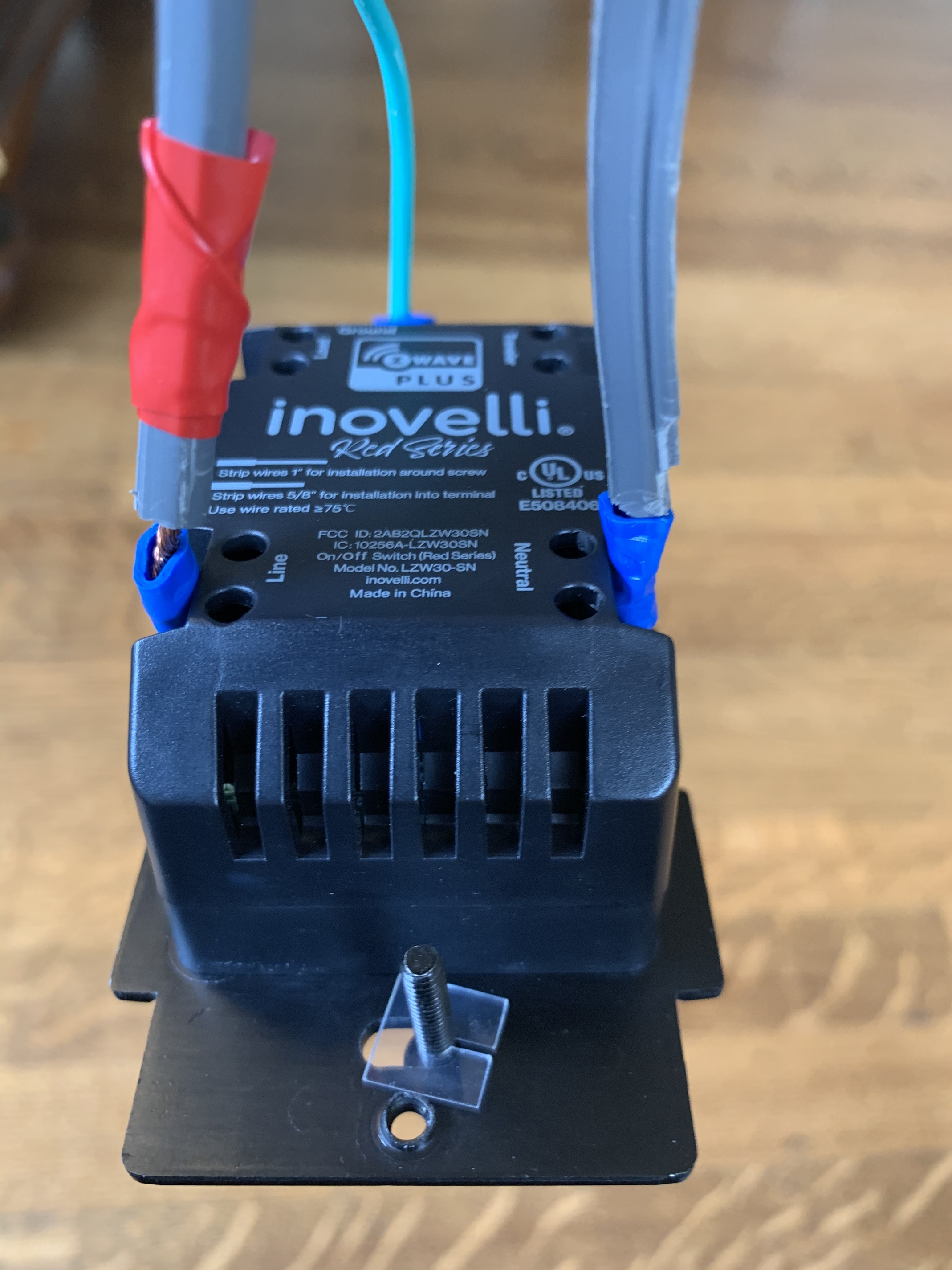
I’ve got an LZW30-SN On/Off Red series on my desk right now spliced into half an old extension cord, and I can confirm that it will communicate with the hub with no load.
“Old extension cord”, as in ungrounded and with just two conductors / prongs?
As for the wire being 14-3, I would guess that 14 is the correct gauge but I typically encounter only white and black conductors and an exposed ground wire, in other words 14-2. The sheath and coppers on the left side of this picture look very similar to what I encounter around the house.
Old as in the female end was cut off for another project and I had the male end lying around. I had the ground hooked up. I’ll tell you a secret though, the ground is only for safety’s sake, the switch will work without it.
Exactly. I have switches from other manufacturers installed properly in boxes as well with no loads, just being used as controllers.
14 would be the standard gauge used for most lighting and outlet circuits. And yes the bare ground isn’t counted in the wire count. If the wire entering that box is in fact 14-2, where does the second black wire go in your photograph in post #5?
Honestly I don’t know yet, and given that this wiring runs behind walls and up through a span of lights about 12’ off the floor I’m not sure I can gain 100% confidence. My limited experience with switch wiring involves, well, more wires! (e.g., 2 complete bundles coming into a box: 2 black, 2 white, 2 ground, etc.) Seeing a small, uneven number of 1 white and 2 blacks has me unsure what I really have. But the main reason I suspect 14/2 is because when I’ve opened up other things at my house I typically see only 2 conductors plus ground. Admittedly that’s usually been an outlet.
I have a 3-prong half-extension cord and I plan to run the same LZW30-SN “bench test” that @Chrisml did. I inspected voltages at the stripped ends, one shows 120V from ground and the other shows 0V, so far so good.
Remember that I am only putting an Inovelli device in an electrical box for the purpose of powering its Z-wave transmissions (no electrical switching). Right now all 3 mystery conductors are currently wire nutted to a common potential. I’m planning to identify a “hot” black conductor and wire it to Line, wire the ground copper to the green terminal (not shown in PDF but I assume it exists), verify if one of the other conductors drops to 0V when I untwist the wire nut and if so wire it to Neutral, isolate/insulate the remaining (3rd) conductor, and leave the other terminals empty.
Does this sound right? Taking two pigtails off the same 120V wire nut and putting them on Line + Neutral is an alternative which doesn’t mess up any current circuits, though it provides no potential drop across the switch so I’m not sure whether the device would function.
Don’t do that, disconnecting the white wire (for example) from the black wire doesn’t automatically make it a neutral. As you mentioned there shouldn’t be any potential, but if something inside the switches isn’t happy you’ll likely fry a switch and potentially arc/smoke/set fires. There’s a possibility that you’ll be running the load of a light or receptacle somewhere else through the switch.
I would however disconnect the wires, measure any potentials with a voltmeter/multimeter and see what in the circuit/house stops working with that nut removed. You’ve already determined the bundle is 120v away from ground, so that white wire is probably going somewhere. There’s also a good chance that once you disconnect the bundle the white wire measures 0v and nothing stops functioning in your lighting circuit, in which case that white wire could be capped somewhere else.
Are the lights in this circuit/room recessed/can/pot lights, or are they traditional light fixtures installed over octagon boxes? It sounds like you might need to grab a ladder and dig further.
I do have one bit of progress to report: I was able to wire my LZW30-SN On/Off Red series (arrived last night) to a test extension cord. It powered up fine.
I was able to associate it to the Abode-based Z-wave network, and then set up an automation to control the set of LIFX bulbs that are the target of my efforts. So I guess question #1 is answered in the affirmative: does LZW30-SN On/Off work with Abode?: yes

:max_bytes(150000):strip_icc():format(webp)/5-your-two-sets-of-stripped-wires-56a49dda3df78cf77283491b.JPG)