Has anyone installed a Red Series dimmer into a 4 way non-neutral setup with two auxiliary switches (GE)? I don’t see this schematic anywhere and I am wondering if it will work. Thanks in advance.
It’ll be similar to the 3-way, but the middle switch will have the two reds connected into Traveler and the two blacks connected into Neutral ports.
First thing we need to do is determine which type of setup you have. We need to find the first box that contains LINE as that will be the best place to install the Inovelli Switch. The switch with the 4-way toggle, will be an Aux switch no matter what. Normally, you’d take the two reds and attach it in the Aux switch. Same for the other lines.
Can you take pictures of your boxes so we can see the wiring and get you the best advice.
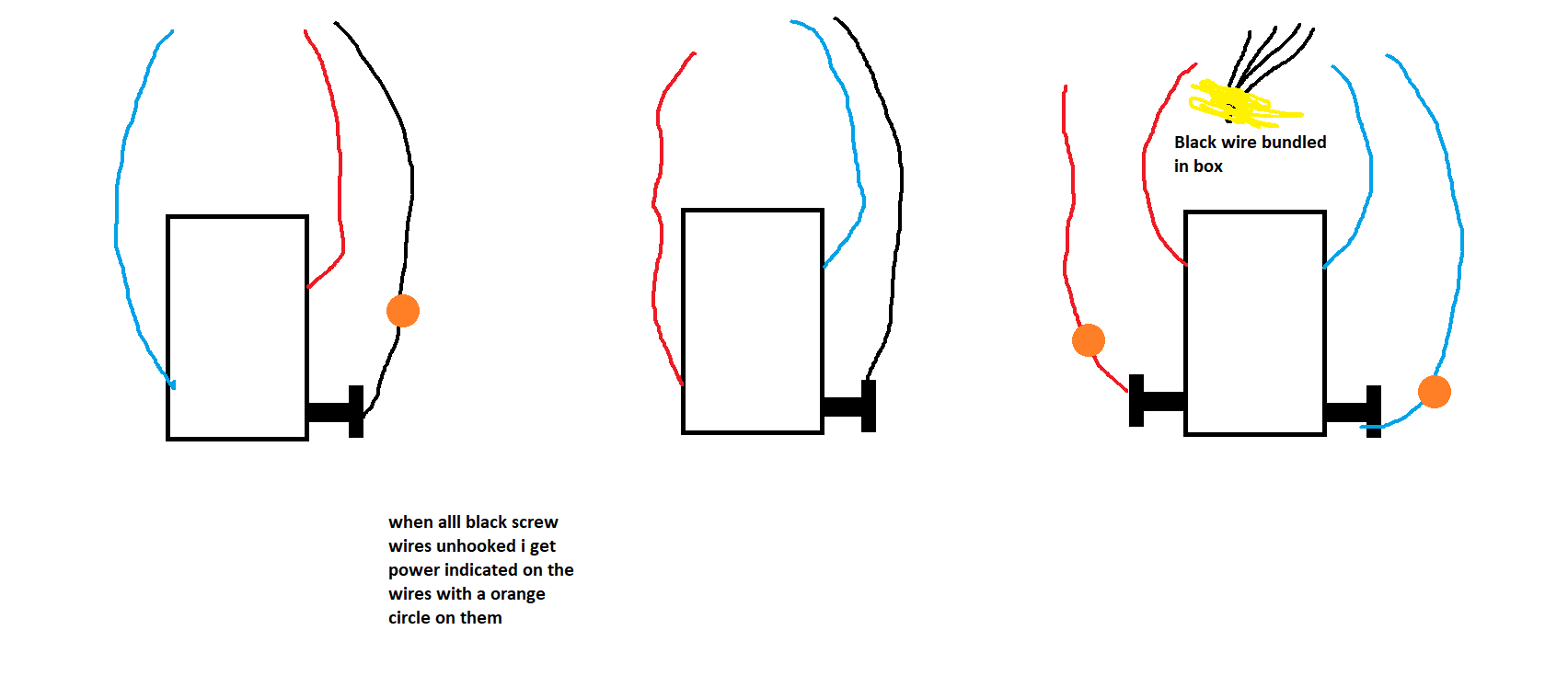
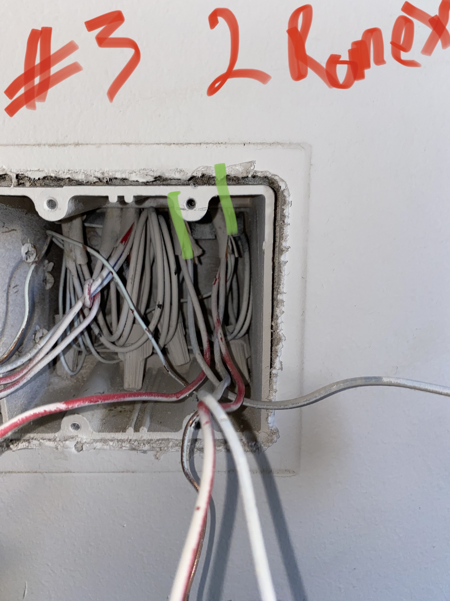
I have all the black screw wires wire nutted and unhooked currently as you can see
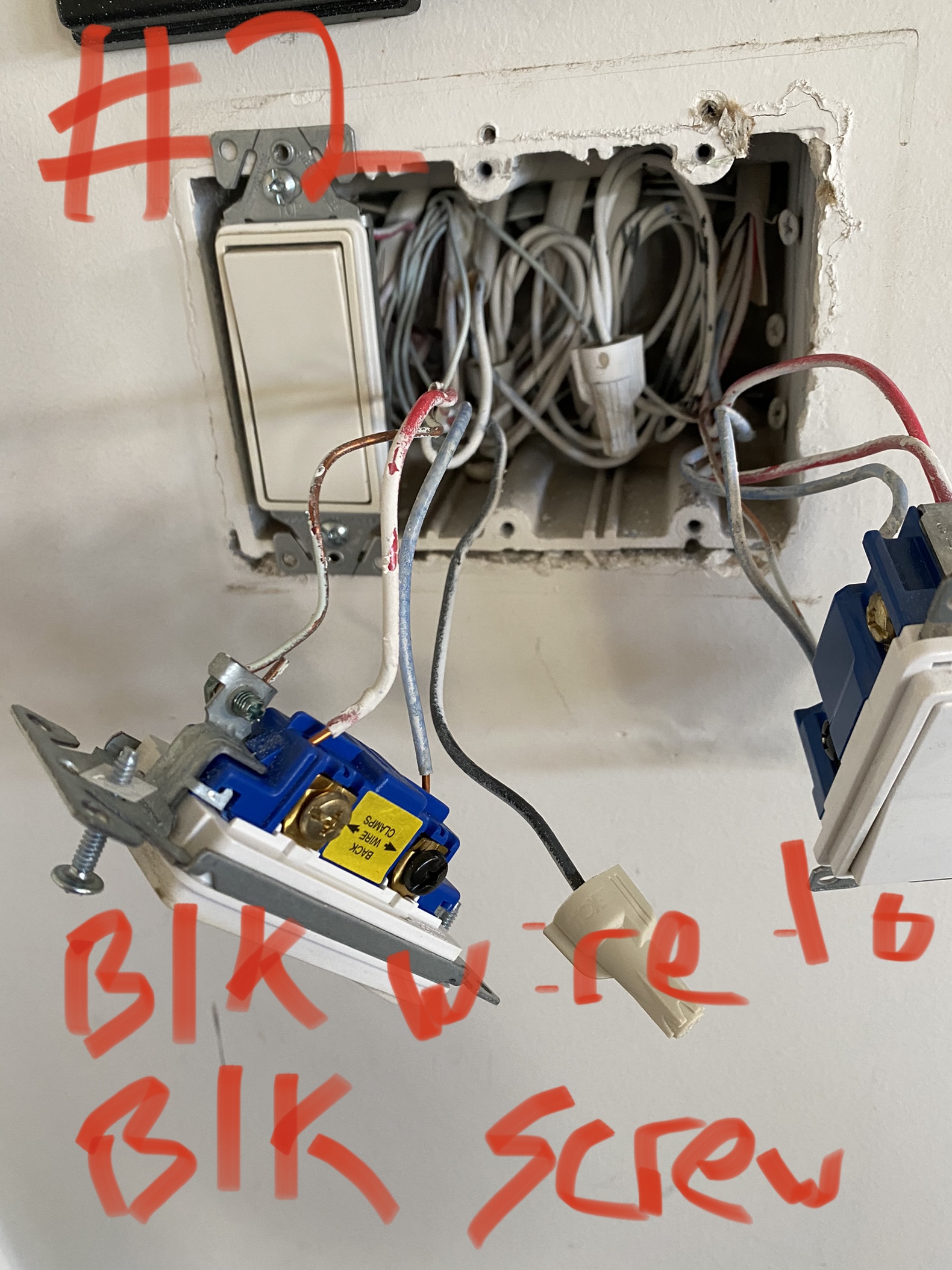
There looks to be neutrals in Box 2. @Bry - Correct me if I’m not looking at it.
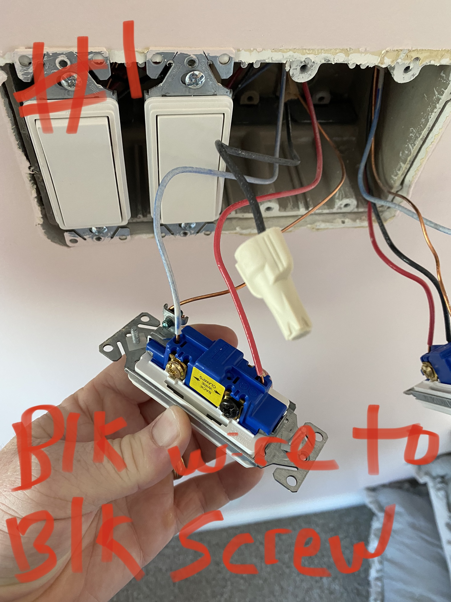
We need to find LINE. Can you confirm which BLK wire has constant hot on it and which box?
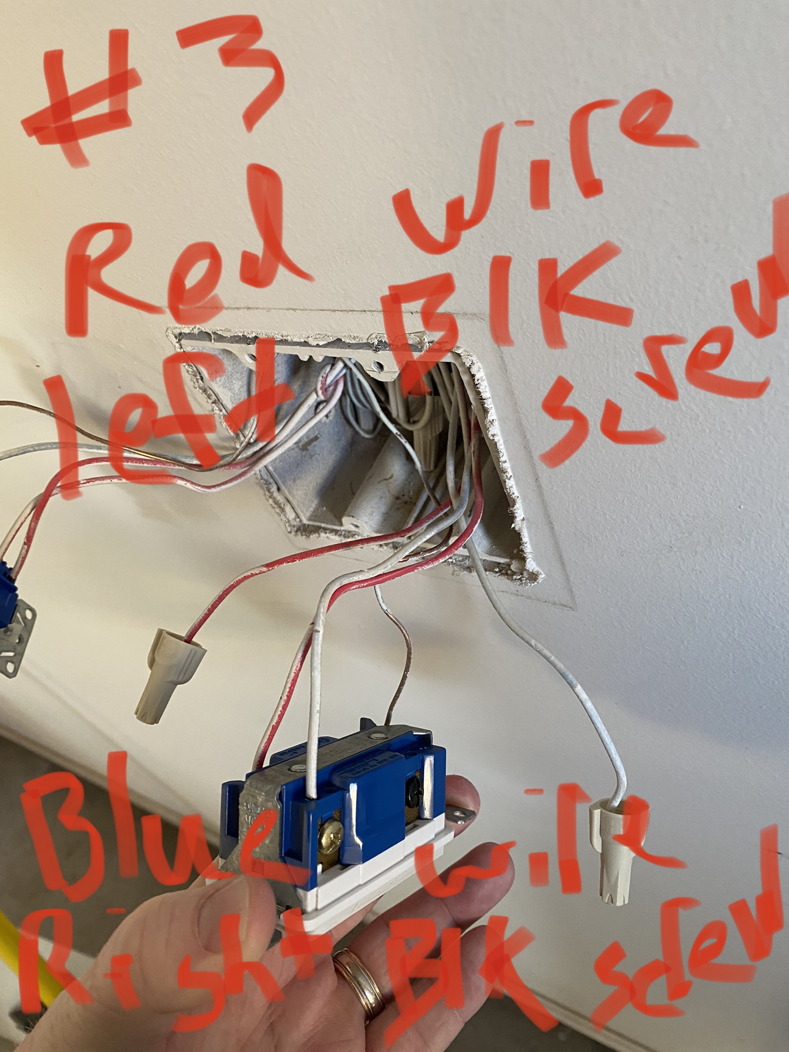
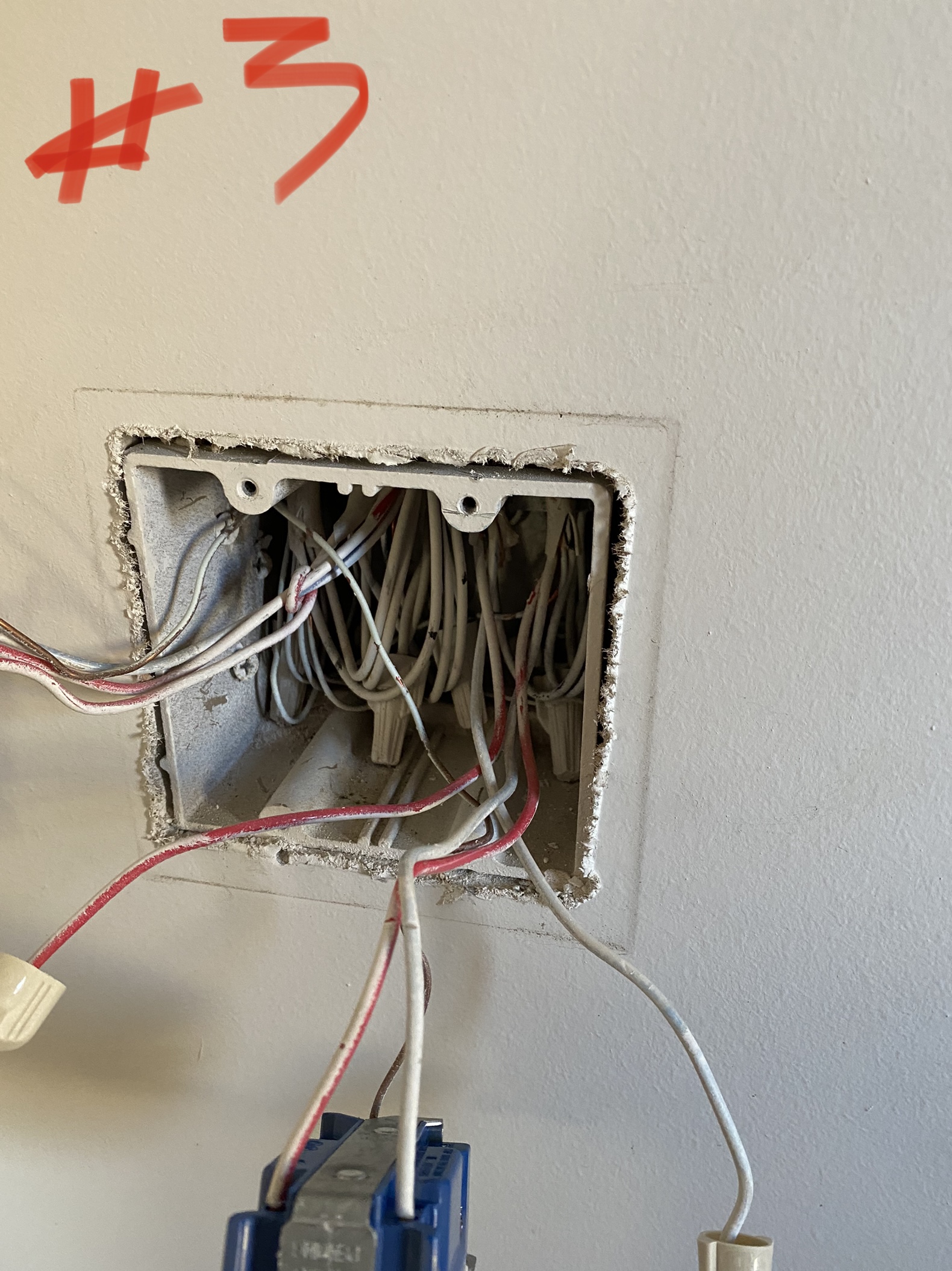
The wires in the back of the box #2 are black wires tied together…so I am not sure if they are neutral wires. In addition there is non in the other boxes. I am not sure what they are used for. When I restore power I get power reading on the black wire on box #1. Interesting though I also get power indicated in box #3 on the red and blue wire that are disconnected from the black screws. I am guessing my meter is picking up residual current somewhere in the box.
So is it safe to say box #1 - black wire is the LINE?
How are you testing? Positive lead to BLK and Negative lead to GND?
Sperry Volt Sensor stick with light.
Then definitely could be picking up. My concern is with BLK disconnected, there shouldn’t be any power being picked up from the Box 3 unless there’s another source in the box that happens to be close. Box 3 is definitely the middle box with the 4-way switch.
Does the same circuit breaker feed the light switches still mounted in Box 1?
A little tough to see into the boxes. The may very well be a neutral bundle in #2 but that doesn’t mean that’s how power is being fed.
OP, for the two 3-way switches (i.e. 3 terminals not counting the bare ground), are all three conductors that are wired to each switch all connected to ONE 3-wire Romex coming into the box? I’m thinking that might be the case but not sure. Plus what I think is your white wire is sort of a funky color, throwing me off.
The reason I’m asking about if for each 3-way switch if there is only one 3-wire Romex connected is because even though most 4-way legs start with power at one end you can bring it into the middle in the 4-way switch box.
So to be clear, for each 3-way switch, are the conductors connected to it (i.e. red, black, white) all from the SAME Romex?
i verified that in box #3 the two i showed as hot are indeed dead with a multi-meter. So box #1 is the only one with power and therefore should be the LINE.

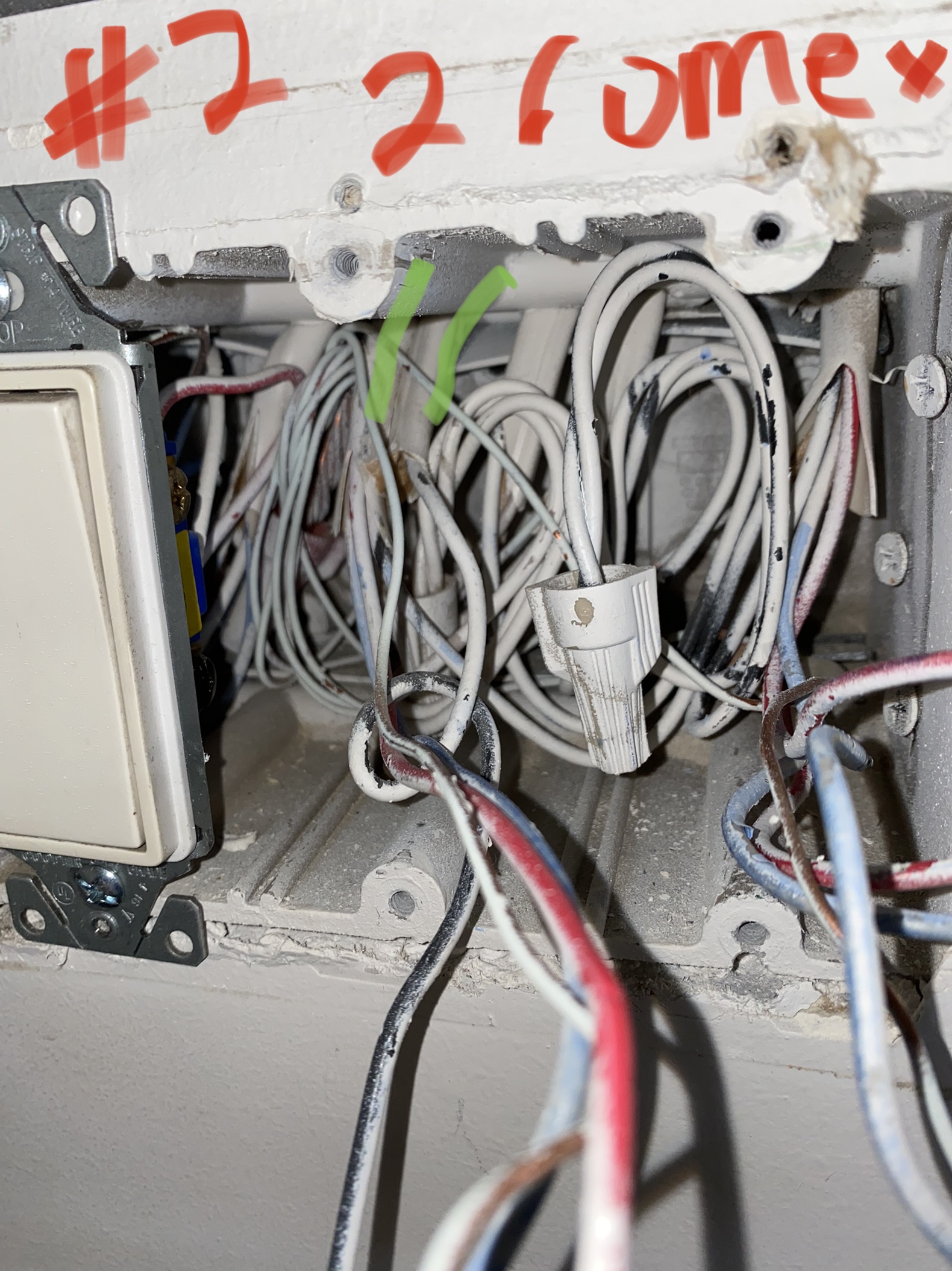
Box #2 with a 3 way has two Romex involved. One with red/blue and the other is black. I think this changes the drawing above. In addition remember that box #1 has the LINE which is the black wire. Does this change the drawing above?
Sorry, misread what you posted. I’m going to remove my last post.
So if you only have one Romex invovlved in #1 and multiple in #2 then power may being fed via #2. If that is the case, then there should be three Romex involved. (It may hard to initially see all Romex involved.)
See if this makes sense. Your #2 then is on the left in the drawing.
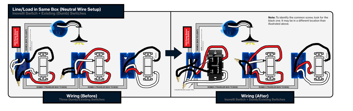
Thanks for the new diagram. Does this mean I have a neutral wire setup per your schematic? I was thinking this didn’t have a neutral wire. Here is a close up of box#2. You will see there are two romex providing wires to the switch on the left. I tried to show this in the pic/diagram.
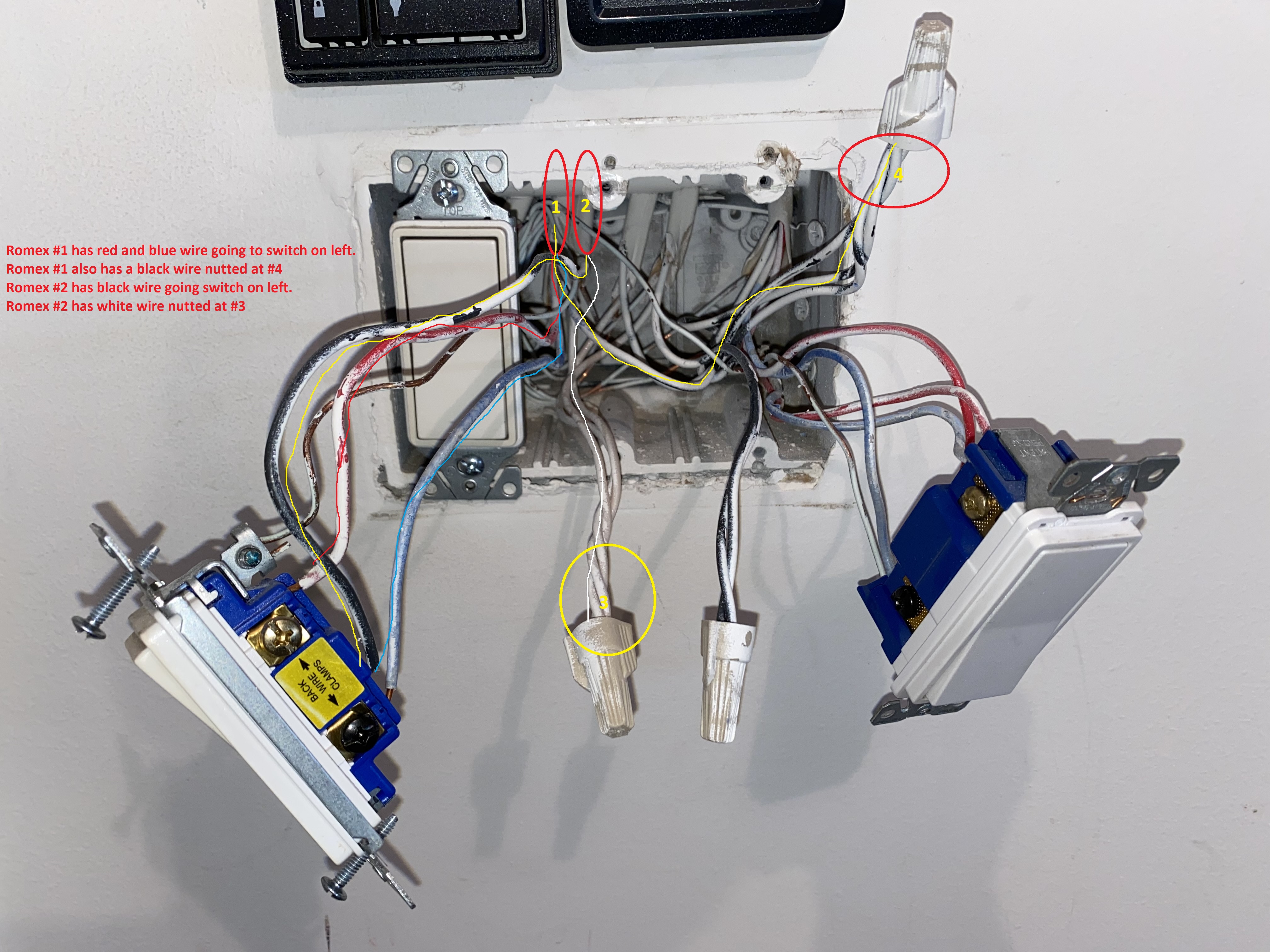
Seeing this does it change the above you provided? Sorry for all the back and forth. I truly appreciate the help.
So the drawing I posted is what I’m thinking at this point but not an absolute. It’s still tough to see in the box but your diagramming over the conductors helped.
Using a METER test between the black #4 bundle and the white yellow #3 white bundle for 120V. Test with the switches in all combinations. I’m thinking that #4 in the hot feed. Confirm that the black from the 3-wire is connected to #4 bundle. This would correspond to the hot being sent to the other side in the Inovelli drawing.
So this would mean that your 2-wire to the light is the #2 Romex in your picture. This makes sense since the black is wired to the black terminal and the white wired to the neutral.
If you do get 120V in your meter testing with the switches in all positions . . .
Then temporarily pull the black from the 2-wire on Romex #2 and touch it to the black bundle 4. The light should go on.