LZW30-SN 3-Way Switched Outlets - Relay not toggling due to voltage issue?

As was the poster of “LZW30 3-Way with outlets,” I am also encountering issues with switched outlets, except with LZW30-SN instead of LZW30 switches and the behavior is different (although potentially related). I have now done in-depth troubleshooting and gathered some interesting data. I would be appreciate of any pointers/ideas you may have.

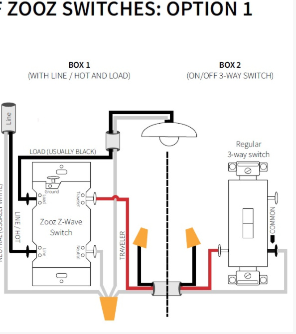
I have the switch wired as outlined in the following image:

I have 120W of LED shop lighting plugged into the switched outlets. For clarity’s sake, when the outlets are powered, I’ll just indicate that the “lights” are on.

There are four possible state combinations between the two switches:

  1. Dumb Switch in state A (toggled down), LZW30-SN in state B (if this were a dumb switch, it would be toggled up). In my case, this setting turns the lights ON. (NOTE: In my testing, this is the state that the circuit enters when I flip the circuit breaker on at the panel)
  2. Dumb Switch in state A (toggled down), LZW30-SN in state A (toggled down). Turns lights OFF.
  3. Dumb Switch in state B (toggled up), LZW30-SN in state A (toggled down). Turns lights ON
  4. Dumb Switch in state B (toggled up), LZW30-SN in state B (toggled up). Should turn lights OFF.

I can toggle from states 1 to 2, 2 to 1, 2 to 3, and 3 to 2 without any problems (the lights turn on/off as expected). The issue occurs when I try to toggle between states 3 and 4, wherein I see the following behavior:

  1. Push the off button on the LZW30-SN - Lights correctly turn off.
  2. Push the on button to toggle the lights back on - Blue switch light turns on, but the lights remain off. Since the switch thinks the lights are already on (as indicated by the blue light), pushing the on button a second time does nothing.
  3. Push the off button - Turns the blue switch light off and turns the lights on. Similar to before, since the switch thinks the lights are off, pushing the off button a second time does nothing (the lights stay on).
  4. Push the on button - Turns the blue switch light back on and, since the lights are already on, puts the switch back into the correct state.
  5. Repeat steps 1 through 4 and observe the same behaviors.

It gets more interesting. There is always some voltage on both the Load and the Traveler wires coming out of the LZW30-SN. When toggling between states 1 & 2 and states 2 & 3, if the traveller wire is carrying the 120v, the load wire reads ~56v. If the load wire is carrying the 120v, the traveller wire reads ~38v. (I would love for someone to explain why I’m reading voltage on the wire that is not supposed to be hot). When toggling between states 3 and 4, if the traveller wire is carrying the 120v, the load wire is consistent; it reads ~56v. However, if the load wire is carrying the 120v, the traveller wire is not consistent - it reads an initial ~54v (rather than the expected ~38v). If I continue to measure the voltage on the traveller wire, it drops a volt at a time over the course several seconds to 38 volts. If I do this before toggling the switch on/off, the lights correctly turn on/off every time. Similarly, it appears that if I wait a long time (several minutes), the voltage on the traveller wire drops on its own (without me holding a meter to it) and the switch works correctly on the next use, but I haven’t yet proven this conclusively.

Given this information, it appears that the switch is putting out more voltage on the Traveller wire than expected when switching between states 3 and 4. The blue switch light turns on/off as expected, but the switch appears to believe that it has already turned the lights on/off (presumably because of the higher-than normal voltage on the traveller wire).

As an additional, interesting anecdote, when the blue switch light is off and the lights are on (Step 3, above), if I measure the voltage on the Load wire, it immediately flips to 120v and the lights turn off - I haven’t thought through/attempted to explain this yet.

I’ve tried swapping with another switch and saw the same behavior.

Any thoughts/ideas???

It’s not uncommon to see “phantom” voltage on the traveler that’s not hot, even with regular, non-smart switch setups. This doesn’t definitively indicate that there is an issue and may be normal. If in doubt, have a licensed electrician check your wiring.

What are your parameters 21 and 22 set to? They should be 1 and 1. Even if correct, I would try resetting them at the switch by changing the parameters and saving, then resetting to the proper setting.

This is all new construction/wiring and I have the full wiring schematic - I’m fairly confident everything is correct. I wouldn’t be surprised to see some voltage in the wire, but I am surprised to see this much. In another location with a switched outlet, there is enough voltage when the LZW30-SN is turned off that a three-light tester shows an open neutral, whereas if I replace the LZW30-SN with a dumb switch the open neutral disappears (I digress though, that’s a separate issue).

Since this is the LZW30-SN (not the LZW31-SN - i.e., it’s not a dimmer, just an on/off switch) it doesn’t have the parameters you have mentioned (I’ve double checked this a couple times just to make sure - and others have reported the same thing). :frowning:

Yep, you’re correct. Those are dimmer parameters only. Sorry about that.

I’ve seen phantom voltage up to 80V or so, but ymmv.

Interesting on the phantom voltage. That’s good to know. What I find intriguing in this case is that if I apply the meter to “drain” the voltage, it gradually drops down to the same voltage seen when in other state transitions (1 to 2, 2 to 3, and vice-versa) and then the switch works correctly. That’s what leads me to believe there is a voltage issue. It is almost as if there is a capacitor holding charge and, if manually drained or if you wait a long time for it to drain on its own, then the switch works correctly.

I do have an LZW31 dimmer on hand - maybe I’ll try configuring it and seeing if that works.

Good for testing, but keep in mind a dimmer on a receptacle probably violates your code.

Phantom voltage bulletin from NEMA:

Turns out, a properly configured LZW31-SN (red series dimmer) works just fine. I was hoping I could just disable the dimmer functionality, but I don’t see a parameter for that… I tried the on/off switch on another 3-way circuit (same configuration as the one outlined above) and saw the same problem. It’s disappointing that the the on/off switches aren’t working - seems like a core feature.

If you set Parameter 1 to 0, it should work similar to an on/off switch in that it will turn on instantly (it will by default change parameters 2-4 to match parameter 1).

I’m really not sure on the rest of this thread, I’ll pass it onto the manufacturer to see if they have any insight.

If you set Parameter 1 to 0, it should work similar to an on/off switch

Yes, that’s how I set it up. Works just like on/off… unless you activate the dimmer :slight_smile: . As @Bry noted, the issue with having the dimmer enabled is that it violates electrical code (given the load is connected to outlets rather than to a light fixture). If the “minimum level” (parameter 5?) could be set to 100, I presume that would effectively disable the dimmer, but the maximum value for that parameter is 45.

@Eric_Inovelli, I appreciate you digging into this - Keep me posted!

One more interesting anecdote I discovered is that the behavior of the switch is dependent on the load. When Hyperikon HyperFixture-4F-40T2 40W LED shop lights are turned on and plugged into the outlets, the switch behaves as outlined in this thread. It doesn’t matter if I have one fixture (40 Watts) or six (240 Watts) plugged in, the behavior is the same. However, when a single ViaVolt 4 ft. 4-Bulb T5 fluorescent grow light fixture (216 watts total) is turned on and plugged into the outlets, the switch operates as expected.

I wonder is using an Aux switch would remedy all of this . . .

I wonder is using an Aux switch would remedy all of this . . .

Potentially. Unfortunately, the wall framing is only wide enough for a single-gang electrical box and I need two switches in the same box. Are you aware of any auxiliary switches that have two switches in the same body (also referred to as “Combination Switches”). I’m currently using this Leviton 15 Amp 120-Volt 3-Way Combination Rocker Switch as my dumb switch. (Note: that I did try swapping this with a standard 3-way dumb switch just to ensure it had nothing to do with the dumb switch - it didn’t make a difference).

I’m not, but you could add a box ABOVE or BELOW the existing if the aesthetics wouldn’t bother you.

Great minds think alike. :slight_smile: I already have two single-gang boxes stacked vertically, one contains a combination switch for exterior lighting and the other contains a combination switch for interior lighting. I think a third box would be pushing it from a usability and aesthetic perspective (I would give up and use dumb switches before doing that).

Not sure what your framing looks like, but can you mount a box on the other side of the stud? Cut a hole for a new work box and then using a long spade bit (wood studs, hopefully) or an installer bit, drill up or down through the stud and fish the Romex through.

@yourang - Could you combine the interior and exterior lights together (or are you using Smart switches)? Probably using smart switches, so this would be a dumb question…

can you mount a box on the other side of the stud?

Unfortunately, there is a door on one side and a window on the other - I literally only have a single, ~3-inch-wide vertical stud bay to work with. This has actually been a headache that complicated the entire wiring plan. Knowing that I couldn’t fit four smart switches in this location and, consequently, that these switches would need to be dumb switches, I wired the circuits specifically with the Inovelli switches in mind. I designed the circuits specifically to ensure the line and load were in the first electrical box (for the smart switch) with just the traveller wires running to the single-gang boxes that contain the dumb combination switches. This is how I limited the number of wires running in the single-gang boxes and avoided exceeding the electrical box capacity.

Could you combine the interior and exterior lights together

Yeah, the exterior lighting is on a smart switch as well - it is likely achievable, but would take quite a bit of finagling in this circumstance. I don’t think it would be worth it functionally (losing independent control of interior and exterior lighting in the name of a smart switch doesn’t seem like the right tradeoff - this is another thing that would push me to use dumb switches).


One option that strikes me is to try a Zooz switch - My understanding is that they’re made in the same factory?, but the wiring diagrams are different (the dumb switch wiring when connected to a Zooz switch looks more like the wiring for an auxiliary switch, but I haven’t compared them closely).

I would assume this uses a different approach to turn the relay on/off… On some forum I saw an Inovelli wiring diagram that used this wiring approach, but it may have been on a different / older model - I couldn’t find it in any current wiring documentation and I didn’t want to try it and risk damaging the switch.

In any case, I’d prefer to get these switches working and I have a ticket filed with the Inovelli team. They’re working to find a path to resolution - Fingers crossed! :crossed_fingers: I’ll keep posting updates here for the benefit of the community.

Hey so I haven’t read the entire thread yet, but just wanted to comment here. Zooz and our Gen 1 switches were made at the same factory, however we moved to a different one.

The schematic you referenced is for their Gen 1 switch which used a neutral wire to trigger the 3-Way setting, whereas their Gen 2’s use the traveler wires.

It will definitely fry the switch if you wire it that way :yum:

Just an update on this thread for anyone who is watching it - It turns out that some light fixtures (e.g., T8 LED bulbs) have built-in capacitors. When turned off, those capacitors store energy for some period of time (in my case it was between 20 and 30 seconds), which is why I was reading voltage on the load after turning it off and the voltage would drop as I was reading it. This impacts the switch’s auto-detection of the switch mode (single pole, 3-way dumb switch, 3-way aux switch) until the stored energy in the capacitor dissipates. I have worked with the Inovelli team and tested a new beta firmware that adds a parameter (parameter 13) allowing you to change the switch mode from auto-detect to dumb-switch. This resolved the issue I was seeing, so once the firmware is formally released, that will provide a solution for those encountering this issue.