You can take a look at this video that shows the symptoms when your are not programmed properly. It demonstrates a couple tests so that you can confirm it is your settings.
Unfortunately this says coming soon! @anon14959390, anything you can share here re setting up via Vera, since @laundrymatt is having an issue programming his switch manually?
Probably will have a link to Hubitat’s website ![]()
I actually had done a factory reset when I first posted this, but I will try again.
Maybe this?
@laundrymatt - Just try changing the parameters before adding it to your Z-Wave network. See if we can get the 4 way to work before adding in the Z-Wave.
So I removed it from Vera, then did a factory reset.
I set 21 to 1 and 22 to 1. Didn’t work, I then moved 21 to 0 and 22 to 2 and the switch didn’t click anymore like it does in multi mode. I then moved both back to 1 and it sounded like it should. But it still doesn’t work perfectly.
The LED works mostly fully now where before today it would not. However if I turn the light on with the smart switch and it turns on, I then turn off the light with a different switch and the light turns off. If I go back to the smart switch and turn the light on the led goes up but no light turns on. If I go back to the dumb switch and flip it the turns quickly turn on, but then turn off and I can hear the smart switch click.
wtf…
Almost back to wiring. In @bry diagram, which switch is the Inovelli going in (L, C, R?). It should be in the L position chasing the line, but R would work too.
The parameters are working, but I wonder if the wiring is just a bit off…
Smart switch is in L where the neutrals and power are. The wires match his diagram exactly, and I’ve hooked up my meter to everything to check probably 50 times now 
@Eric_Inovelli @EricM_Inovelli @JohnRob - Any ideas? Seems like the parameters are taking the fact that the switches work somewhat. Only other thing I can suggest is Aux Switches…
I did buy some aux switches so I can use them where I don’t have neutrals, but i can try them here as well.
It’d be worth a shot…then you have to set it up for 3/4way momentary vs. toggle.
That is exactly what is described in that video I posted above, indicating that your switch type parameter is not set correctly.
@laundrymatt - Perhaps take a video of you configuring the para 22/23 so we can watch.
From what I’ve read this is what I think I know:
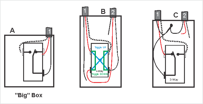
In box “B” the two blacks are said to go to a 120V bundle but I can’t see any bundle not drawn here.
@laundrymatt can you look at the attached and tell me where it is wrong and where the unconnected wires go.
Its best if you use nomenclature Box “B” Cable “2” Black Could be B_2_Bk
John
I uploaded pictures earlier that showed the bundles and a video earlier as well that showed some, but I will upload two more right now so you can see.
1st Video is of how I program, hopefully it’s correct. (Ignore the first part as I showed the wiring but I do it in more detail on the next video)
2nd Video is of each box so you can hopefully see.
@JohnRob Here is the short version. C only has one relevant 3-wire. It also has a bundle of black hots, a neutral bundle and another 2-wire going to the light. The two blacks in B are wire nutted.
@laundrymatt - You held the config button until yellow when saving it right? (video ended just prior).
@harjms - Sorry, I cut it off too soon, yes. It goes yellow then I let go and it flashes after that.
Well now I’m really confused. I hooked everything up with add-on switches. I set parameter 23 to 2 for aux setup. The Inovelli switch works perfectly, however both aux switches do absolutely nothing.
I ran all whites to the neutral bundle, kept line where it was and red traveller on traveller, then moved the black to the light to load. Next box I put both reds on one screw and both whites on one screw, and the last box was 1 white on a screw and one red on a screw. All matches the diagrams.
Something has to be off…