LZW31-SN 3 Way Strange Behavior - Odd voltage readings

Hello,

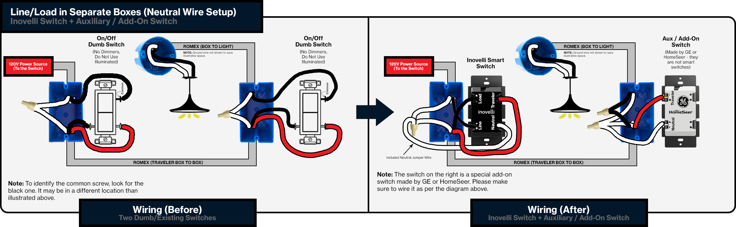
I purchased 10 LZW31-SN and 10 LZW30-SN a few months ago and the On/Off switches have been perfect but I seem to have continuous problems/bad luck with the installation and functionality of the LZW31-SN in three way switch scenarios. All of the switches were installed by an electrician during our home remodel and state wiring to be good and that the switches themselves are faulty. I have 4 dimmers in a single pole setup that are all working great.

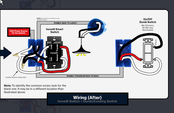
Jist is the three way switches all become unresponsive and lose power when turning the dumb switch on. There is neutrals in both boxes with the Hot appears to be coming in on the smart switch box and the electricians claim all is well with the wiring in those boxes.

I have tried inclusion/exclusion on the faulty switches multiple times, factory reset them all, upgraded the firmware twice on all (latest 1.56 on the LZW31-SNs), upgraded the firmware on the Nortek HUSBZB controller and verified that the parameters for 21 & 22 are both set to 1 both by setting through zwavejs2mqtt in home assistant and also manually through the config button(also toggling to a different parameter and back) at each prior step. The switches have also recently started acting up further where if the lights are turned off from the LZW31-SN you can hear the relay click but the LED stays completely lit as if the light was on and when turning back on the lights are about 10% dimmer and stay that way until either the dumb switch is toggled (killing power?) or pulling the airgap. I tried updating the .bin file again on both as I believe that file is for the LED functionality but no change after doing so.

Lights: https://www.homedepot.com/p/Commercial-Electric-Ultra-Slim-6-in-Selectable-CCT-Canless-Color-Integrated-LED-Recessed-Light-Trim-Downlight-900-Lumens-Dimmable-53807101/306179204

(LED 15W) 6ea on 2 LZW31-SN and 4ea on an additional 2 LZW31-SN. I also have a LZW31-SN in multi-switch running 6 more of these that is functioning ‘close to normal’ in the sense that they work but I was unable to have the LZW31-SN located where I would like as there was no neutral in that particular box and the electrician was unable to get the light functioning with having the dimmer in the non neutral box and installing a GE Aux switch in the box with the neutral. I have 4 GE add-on aux switches 12723 that they were unable to get working where the dumb switches currently are. I’m not sure their comfort level with z-wave switches and they seem unwilling to delve into it further so am seeking a second opinion here on where to go next.

Dumb switches are https://www.lowes.com/pd/Legrand-radiant-Single-Pole-3-Way-White-Compatible-with-LED-Rocker-Light-Switch/1000001252

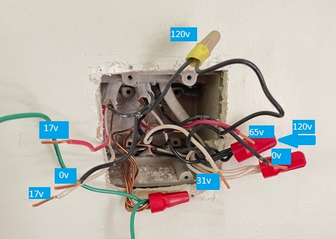
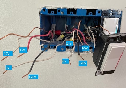
Using a multi-meter I took the readings from two of the ‘bad’ switches & their dumb counterparts and received the following voltages.

**Smart Switch On - Dumb Switch Off**			
         Smart Switch			

Traveler 72v Load 98v
Neutral 0v Line 120v

         Dumb Switch				

Line 98v
Traveler? 70v Common 98v

**Smart Switch Off - Dumb Switch Off**			
         Smart Switch		

Traveler 72v → 0v Load 7v
(pulsing) 72v → 0v
Neutral 0v Line 120v

         Dumb Switch			

Line 7v
Traveler? 72v → 0v
(pulsing) 72v → 0v Common 7v

**Smart Switch Off - Dumb Switch On** (no power at Smart Switch anymore)			
         Smart Switch			

Traveler 3v Load 120v
Neutral 0v Line 120v

         Dumb Switch			

Line 120v
Traveler? 3v Common 3v

**Measurements to wires with both switches disconnected**			
         Smart Switch			

Traveler 32v Load 60v
Neutral 0v Line 120v

         Dumb Switch			

Line 60v
Traveler? 32v Common 0v

Another curious site is when the lights are on they are only reading 1.6W for parameter 66049.
When I set the logging on and to Silly this is the only output:

2021-05-11 20:46:00.210 INFO ZWAVE: Controller status: Scan completed
2021-05-11 20:46:00.211 INFO ZWAVE: Network scan complete. Found: 13 nodes
2021-05-11 20:46:00.231 INFO ZWAVE: Node 39 ready: Inovelli - LZW31-SN (Red Series Dimmer)
Dumb switch turned off here for node 39 & 36 and then turned back on ~10 seconds later
2021-05-11 20:46:13.709 INFO ZWAVE: Node 39: value added: 38-0-targetValue => undefined
2021-05-11 20:46:13.712 INFO ZWAVE: Node 39: value added 39-38-0-targetValue => undefined
2021-05-11 20:46:13.718 INFO ZWAVE: Node 39: value updated: 38-0-currentValue 96 => 96
2021-05-11 20:46:16.613 INFO ZWAVE: Node 39: value updated: 50-0-value-66049 1.6 => 1.6
2021-05-11 20:46:17.145 INFO ZWAVE: Node 36: value added: 38-0-targetValue => undefined
2021-05-11 20:46:17.148 INFO ZWAVE: Node 36: value added 36-38-0-targetValue => undefined
2021-05-11 20:46:17.153 INFO ZWAVE: Node 36: value updated: 38-0-currentValue 99 => 99
2021-05-11 20:46:20.046 INFO ZWAVE: Node 36: value updated: 50-0-value-66049 1.6 => 1.6
nothing after this

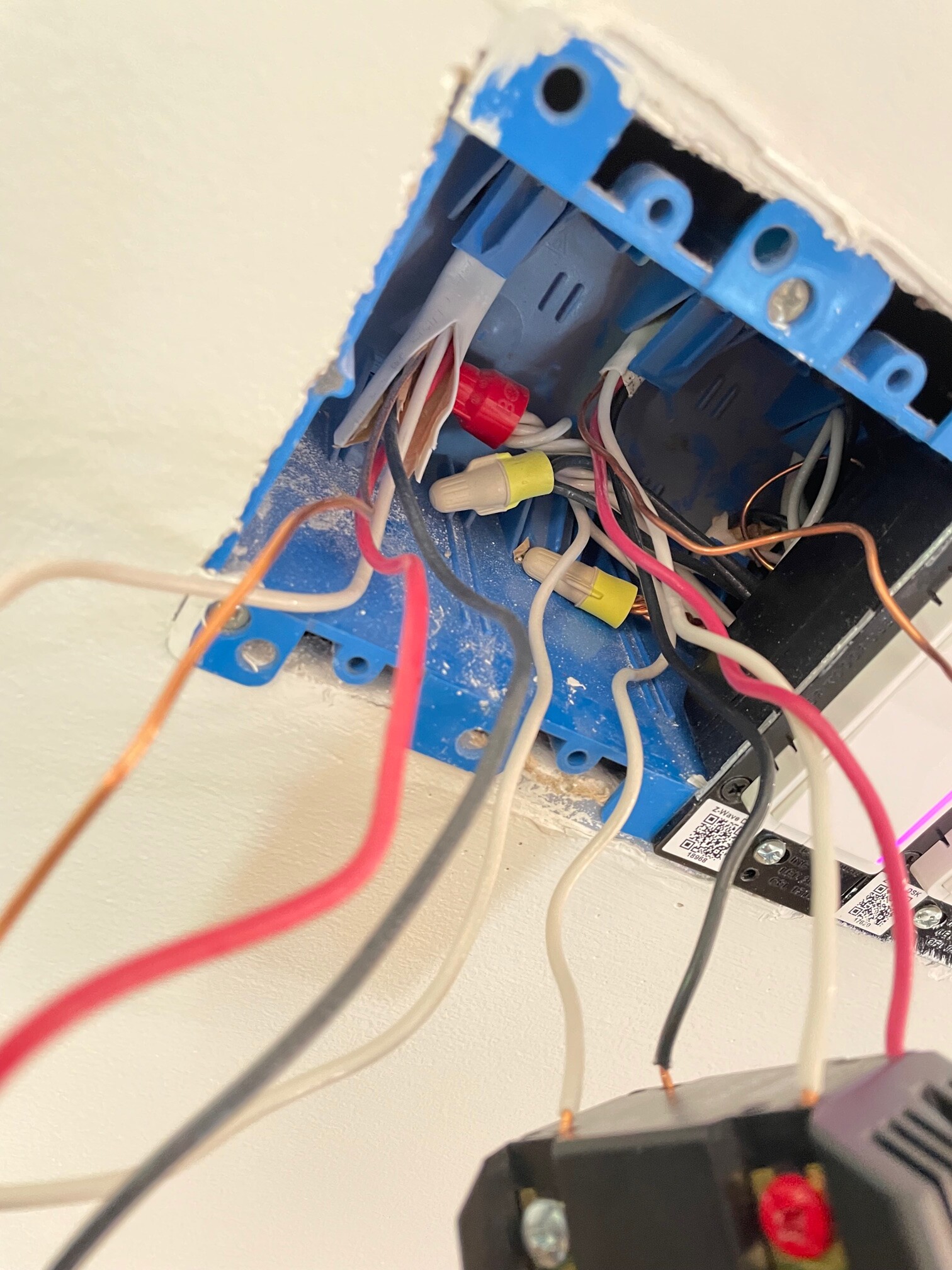
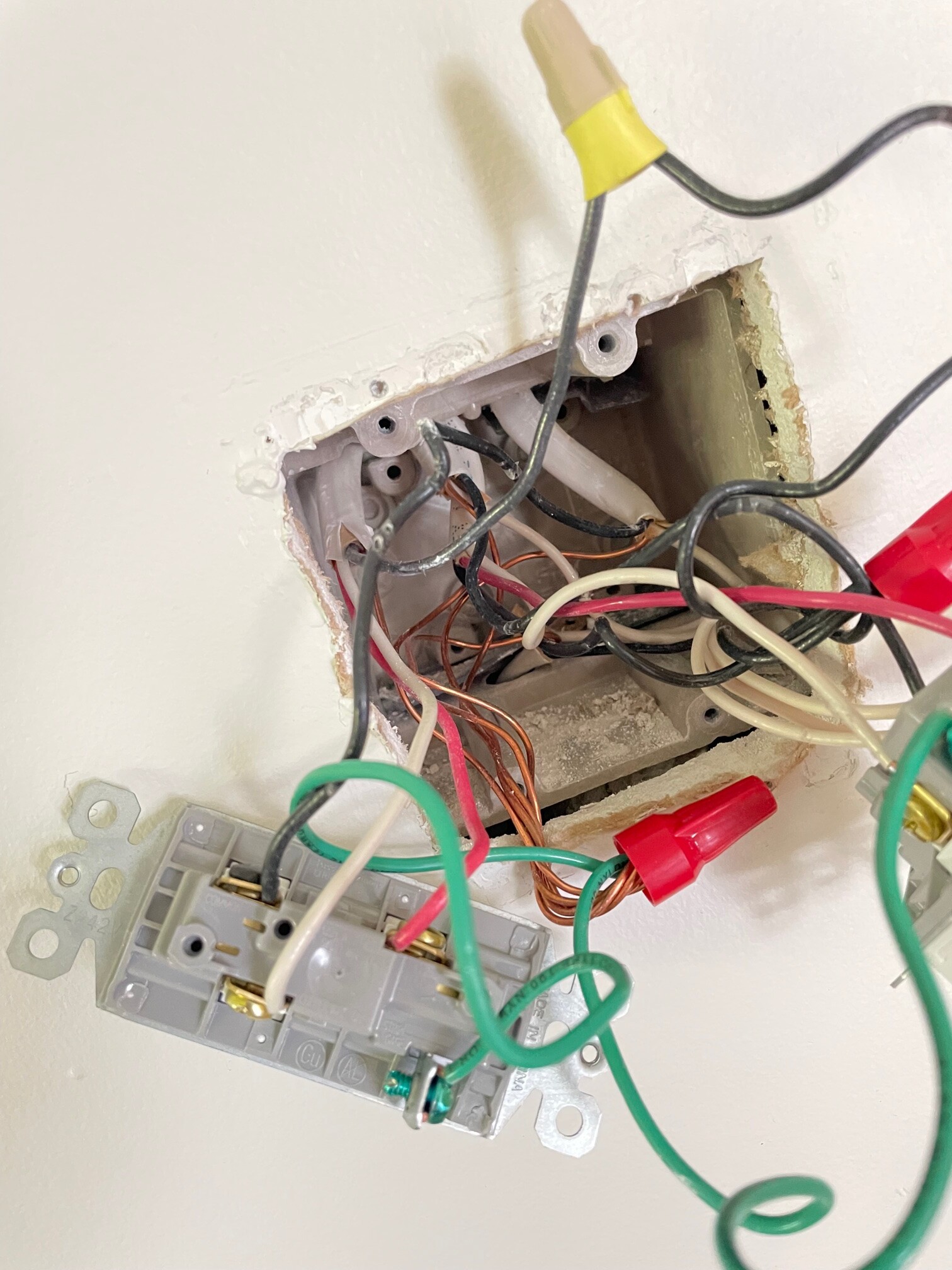
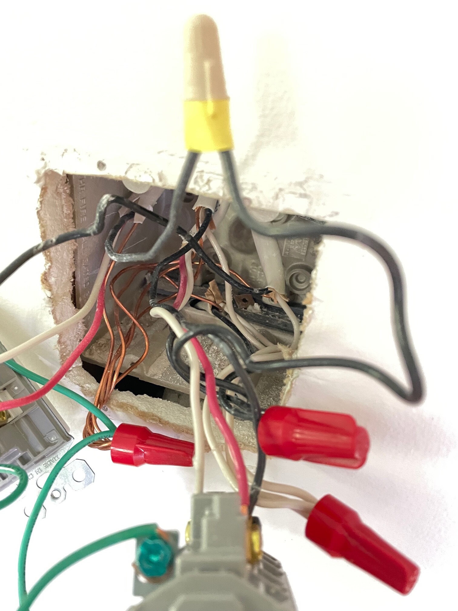
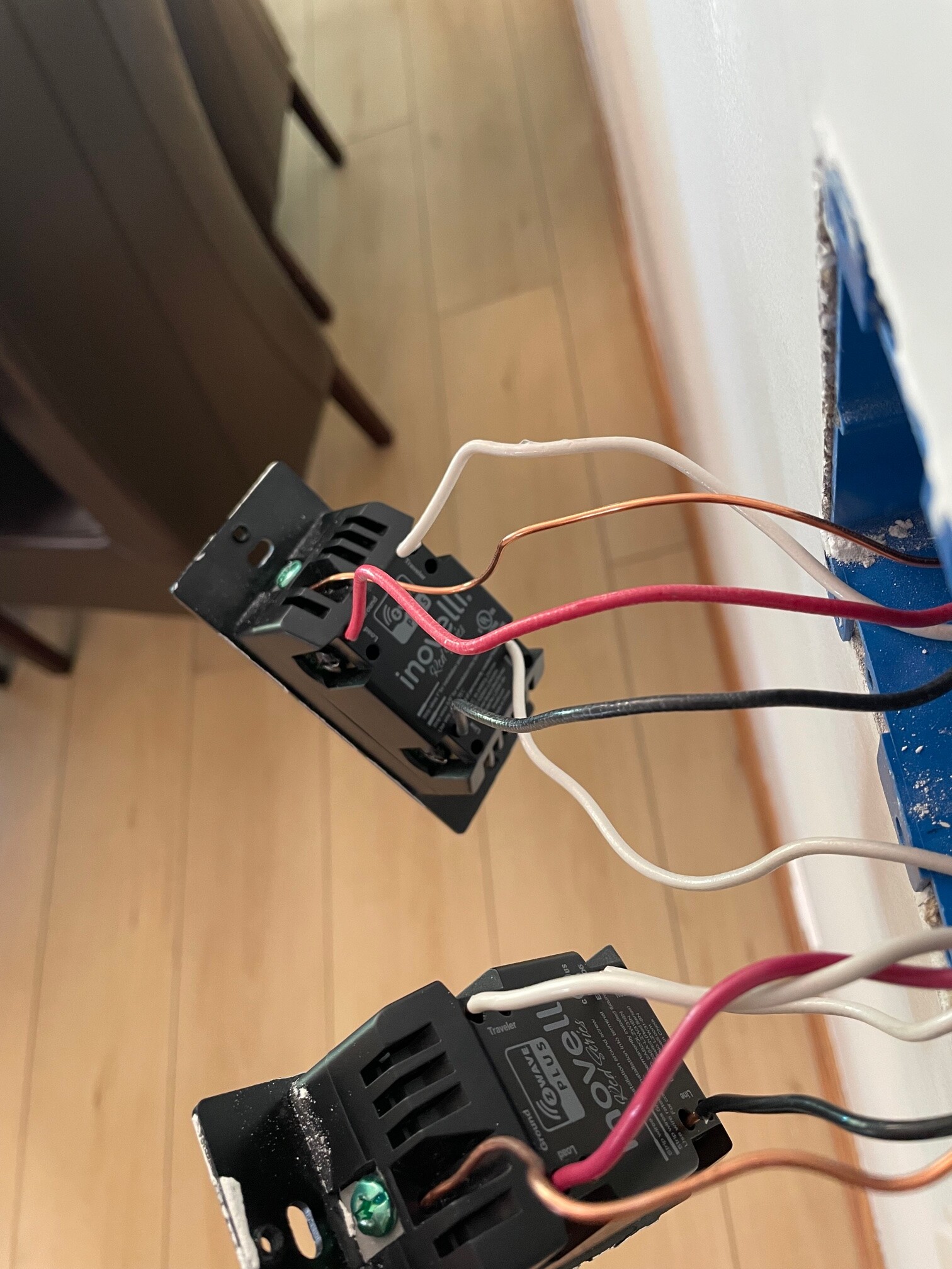
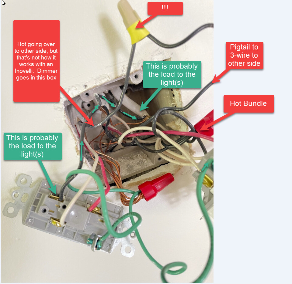
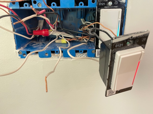
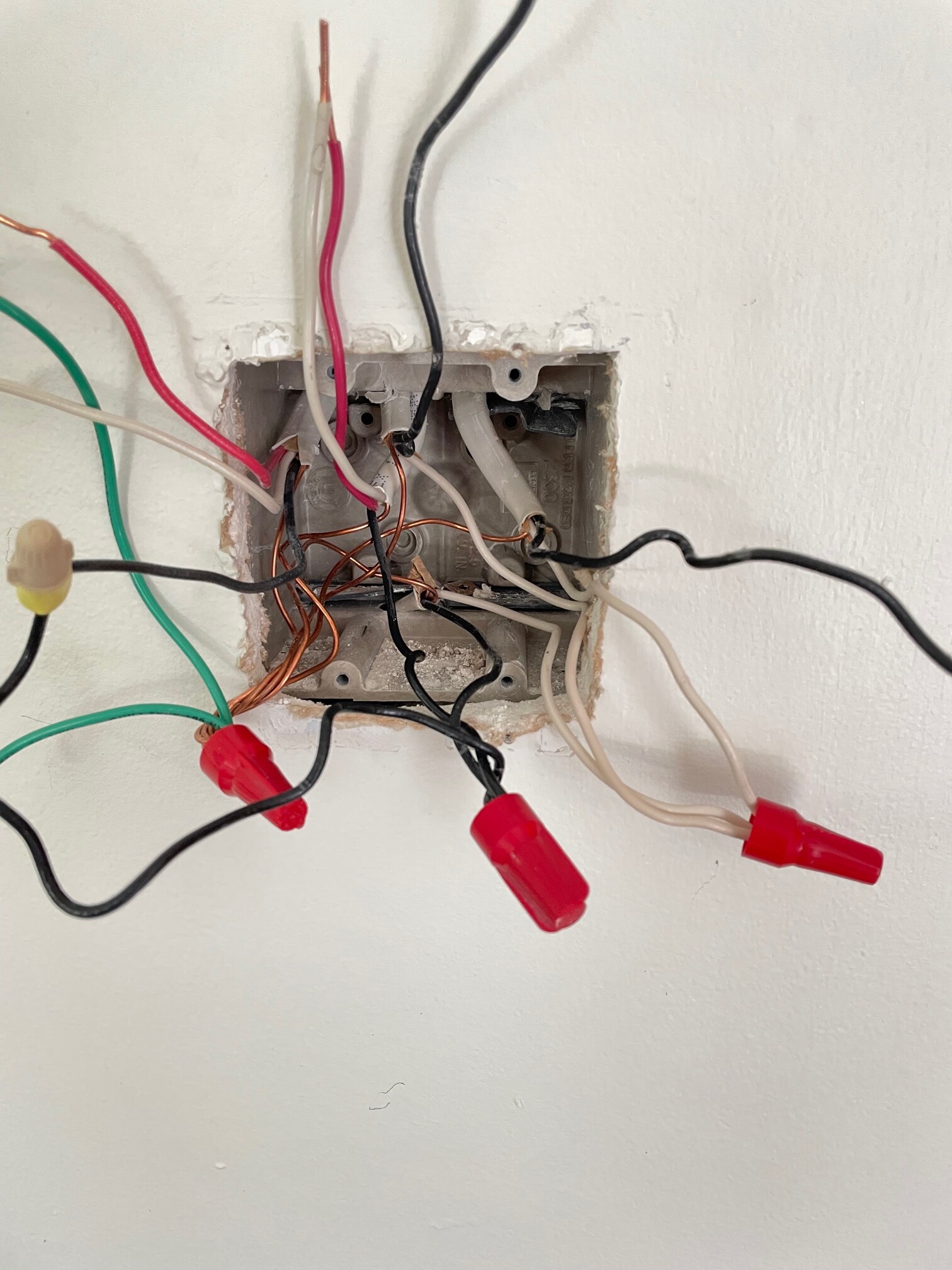
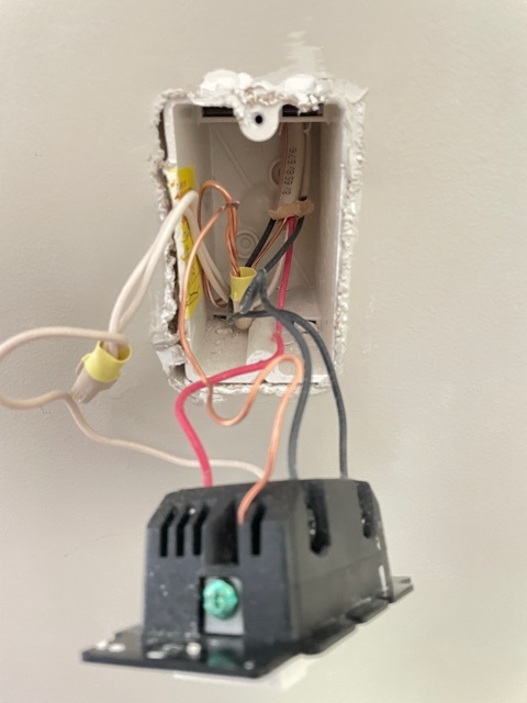
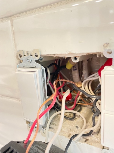
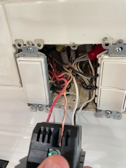
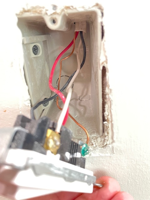
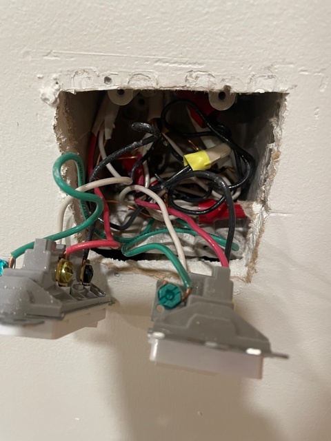
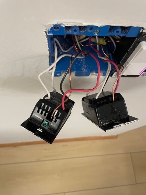
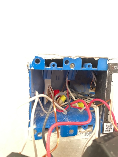
Here is pictures of the dumb switch & dimmer switch (on the dimmer switch image, there are two other LZW31-SN in single pole that are on a different circuit)


I’m at a bit of a loss from where to go so wondering if a) you may think there is a wiring issue based on the odd voltage readings(in my opinion, but not an electrician) or b) provide some additional troubleshooting guidance. I have not moved any wiring around at this point as I’m not confident with what making those changes does but can do so if you believe it’s needed.

Thank you!!!

So for the 3-way dimmers having an issue losing power, was the issue always present or did something change? Is it possible it was always present but you didn’t notice it as you were only using the dimmer, not the dumb switch?

When you say the dimmer loses power, that means even the dimly lit when off LED bar goes completely out? Without any wire diagnosis, my first thought is that the switch is wired incorrectly. It sounds as if flipping the dumb switch is killing power to the Inovelli. If this is the case, when you think the Inovelli is dead and you then flip the dumb switch, do you see the Inovelli power back up with the LED flashing Red, Green, Blue (just like if you had pulled the air-gap with the power on)?

Voltage measurements, with the exception of is there 120VAC present or not, aren’t of any value. 3-way switch legs typically carry ghost voltage due to inductance, so unless you are using a low impedance meter (which most don’t’ have), I wouldn’t be concerned at this point with the 72v +/- that you’re seeing.

One voltage test you can perform is to check the voltage across the line and neutral terminals of the Inovelli. When it’s powered up (LED bar is lit) you should see 120VAC. Now go flip the dumb switch. Do you still have 120VAC across the Inovelli’s line and neutral?

A minor point, not really relevant here but just so you understand . . you don’t have neutrals in both boxes in a three way, at least related the the switch leg, unless you route them if the load is in the far box. There is only a neutral on one side with a line/load in the same box. That’s fine, that’s just how it works with a three way.

I just noticed something I missed before. Are the dumb switches you are using lighted?

Hey Bry! Thank you for the reply.

  1. the dumb switches are not lighted
  2. when dumb switch is flipped ‘on’ there is no power at the Inovelli switch aka LED is not lit, air gap doesn’t restore power and toggling the dumb switch back to ‘off’ causes the LZW31-SN to power back on.
  3. when LZW31-SN has power its 122V from line to neutral - when flipping the dumb switch there is still 122V from line to neutral
  4. I was told by the electricians that there were neutral wires in both boxes so that is where that guidance came from. I can verify through my general contractor if you believe it’s necessary to know for sure.

Let me know if you need any more information!

Ok, so it sounds as if you have constant power to the Inovelli but something else is going on with the dimmer. No need to follow up regarding where neutrals are.

If you like, we can take a look at your wiring. Let’s just do this for one pair that is problematic. I saw that you posted pics before but lets try again. Pull the switches out as far a possible and take pictures so I can see all the way into the back of the box where the Romex comes in. Sort of like the last picture you posted, but I need to see the connections to the switch too. Also let me know if we’re looking at the right or the left switch. We need pics for both the Inovelli and the dumb switch.

Hey @Bry, thank you for the quick reply and sorry for the delay. I will be at my desk for the remainder of the day so can run tasks pretty quickly if needed(work from home).
Here are the images requested - i primarily focused on the Left switch but you can see wiring for both.

An odd thing I noticed is that the neutrals in the 4 gang appear to be wired together with the neutrals from the other two dimmers but those two dimmers are on a different circuit. I’m not sure if that matters but an observation.
Also, do you see any oddities with the fact that the voltage is pulsing on both ‘traveler’ wires when both switches are off?

Thank you again

Thanks. I’ll take a look at the pictures.

So do I understand correctly that you have a box with four switches and ALL of the neutrals are tied together, but the switches on that box that are using the neutrals are on different CIRCUIT BREAKERS?

If that is truly the case, if you are in the US, that would violate the NEC. It poses a potential risk because you can potentially return to the panel via the wrong neutral. The only place that neutrals from different branch circuits are to be tied together is at the breaker panel.

That being said, I don’t know if that would cause the issue you are experiencing. If either of those circuits is using an arc fault breaker, sooner or later you’re going to have issues with breakers tripping.

Will look at your pics.

That is correct - it also does not appear either circuit has an AFCI breaker in the box so I will bring it up with the contractor to let him know.

Took a look at your pics, specifically looking at the Inovelli on the left and the dumb switch on the left. I’m presuming they are paired. This is my impression without having conducted any voltage tests, etc.

I don’t believe your switch is installed in the proper box. They’re backwards. The Inovelli goes in the other box. Going to ask @harjms to double-check me.

It seems to me that the line (where the hot originates for this leg) starts in the box with the dumb switch. If you look at the dumb switch box you’ll see the black from the 3-wire (probably going to the other switch) is pigtailed to a black bundle, which is probably the source line. In a traditional 3-way dumb switch wiring configuration, that’s how you would do it by first sending the hot to the other side, but you don’t do that with an Inovelli.

So if your line is in that box, your Inovelli goes in that box. But what your electrician did is try to power the Inovelli with the hot sent over the black. And then to make matters worse, he grabbed the neutral from that neutral bundle in the box. I’d normally ask if that’s even the proper neutral, but since you pointed out that neutrals from two branch circuits are improperly bundled together, well . . nvm.

Did your guy have access to the Inovelli wiring diagrams? If I’m correct, unfortunately, this isn’t done properly. Here is the wiring diagram that should apply if my initial diagnosis is correct. This is with the Inovelli in the box where the dumb switch is presently:

image

This drawing might make it easier to understand what I think I’m seeing in the dumb switch box:

Hope this helps.

BTW, NEC 300.3(B) or 310.10(H) for that bundled neutrals issue.

2 Likes

Yes, I sent them the wiring diagrams by PDF to their phone and also printed out the whole PDF and they had the wiring diagrams that came with the switches.

Is there any way to have the Inovelli work where it sits currently with utilizing an aux switch in the current dumb switch location or putting an Inovelli on/off in that location? The reason I went with smart switches was to have the lights be dimmable by switch in their current location and also have the scene control there.

Attached are pictures of the voltage readings with the switches disconnected and also the Neutral bundle.

IMG_0136
IMG_0137
IMG_0139

I agree that the box with the Inovelli is wired wrong. There is a 3-conductor cable coming in on the top left and that device should only be connected to that cable since that cable is the only cable in the 3-way circuit. The neutral wire from the other circuit wires on the right is done wrong and should not be done. Never get that electrician back because they’re too stupid to understand the wiring and then wire things correctly.

https://community.inovelli.com/uploads/default/original/2X/5/58defe1e9bdbe5139d61d3d4a169b101b01eca21.jpeg

In this box,
It appears the left cable is the 3-conductor to the other box. Hot is being fed to the Inovelli on the black and red and white are being used as travelers. But, there is no neutral to the other box so the Inovelli doesn’t have a neutral.
The middle conductor is the power.
The right conductor is the light load wire.
Inovelli goes in this box. Red and white to other box are used as travelers and black is the load return wire from the common on the dumb switch.

1 Like

I moved everything out of the way to try to get a better picture of what’s in that box as the electricians stated that neutrals were run to both and I’m seeing 5? romex come in? I really appreciate your help

Yes, you can put an aux switch in the grey box. Hook it to the 120V yellow marette and the red as the traveler. Hook the white wire to the load wire, which should be the black sticking to the left side. You should/can put black tape on the white wire to indicate it’s not a neutral, but don’t have to for it to work. 120V hot goes to the “neutral” on the aux switch. Sounds wrong, but thats how it works.

In the blue box hook up the Inovelli with the black to power and the white to load and the red to the traveler. Set it to non-neutral and aux switch.

1 Like

@PJF Thank you, my general contractor is en route right now so we will try that and I will update you.

If I take pictures of another box(or two) they are having issues with would you be able to assist? - same problem on both.

That makes it clearer. In that box,
Both 2-conductor romex at the top appear to be loads.
Both 3-conductor romex at the top appear to go to another 3-way switch.
The 2-conductor romex at the bottom is the line power.

The other boxes with the other 3-way switches effectively don’t have a neutral, even if there is one in the box it’s not for this circuit and can’t be used in this circuit.

1 Like

Whether or not you can reverse the switches depends upon your configuration. If you have a line and load in different boxes (which is not the case with the leg I looked at), you can use this diagram and an Aux switch:

When you have a line and load in the same box, you can’t do that because you only have three conductors between the two boxes, and you’d need four, hot, neutral, traveler and load. A possibility might be wiring it as a non-neutral to drop a conductor, but that may induce further issues. An alternative would be to use two Inovellis and control them via association. That way you are just sending a hot and neutral to the far box to power the switch. I don’t use association, so if you decide to go that route, someone else will need to provide that guidance.

The other alternative to the line and load in the same box, IF YOU HAVE A HOT/NEUTRAL in the box where the Inovelli presently is (and by that I mean ONE ROMEX with both) would be to take that switch leg off the feed from the dumb box and start it in where the Inovelli presently is, turning it into a line/load in separate boxes. The same diagram above would apply.

1 Like

If you want to use the line power in the blue box then you can keep using the dumb switch and that can be wired in a 3-way like you want. I’m pretty sure there is a line power conductor in that box.

Thank you - my GC is here right now wiring the Aux switch.

That line power goes to a separate circuit though so I imagine that would be kind of a no no though right?

Here is two images of the other location having the same issue:


And here is a box where the LZW31-SN is currently working fine, but I would like to move it to where the dumb switch currently sits and have an Aux switch where the LZW31-SN is


Well, you do this,

In the after the Inovelli box is the blue box and the dumb switch box is the grey box. In the dumb switch box you only use the 3-conductor romex on the left and the 2 conductor romex going to the load. The other wires go to the other switch circuit only.

This is how you’d wire an aux switch, again in the after picture left is blue box and right is grey box.