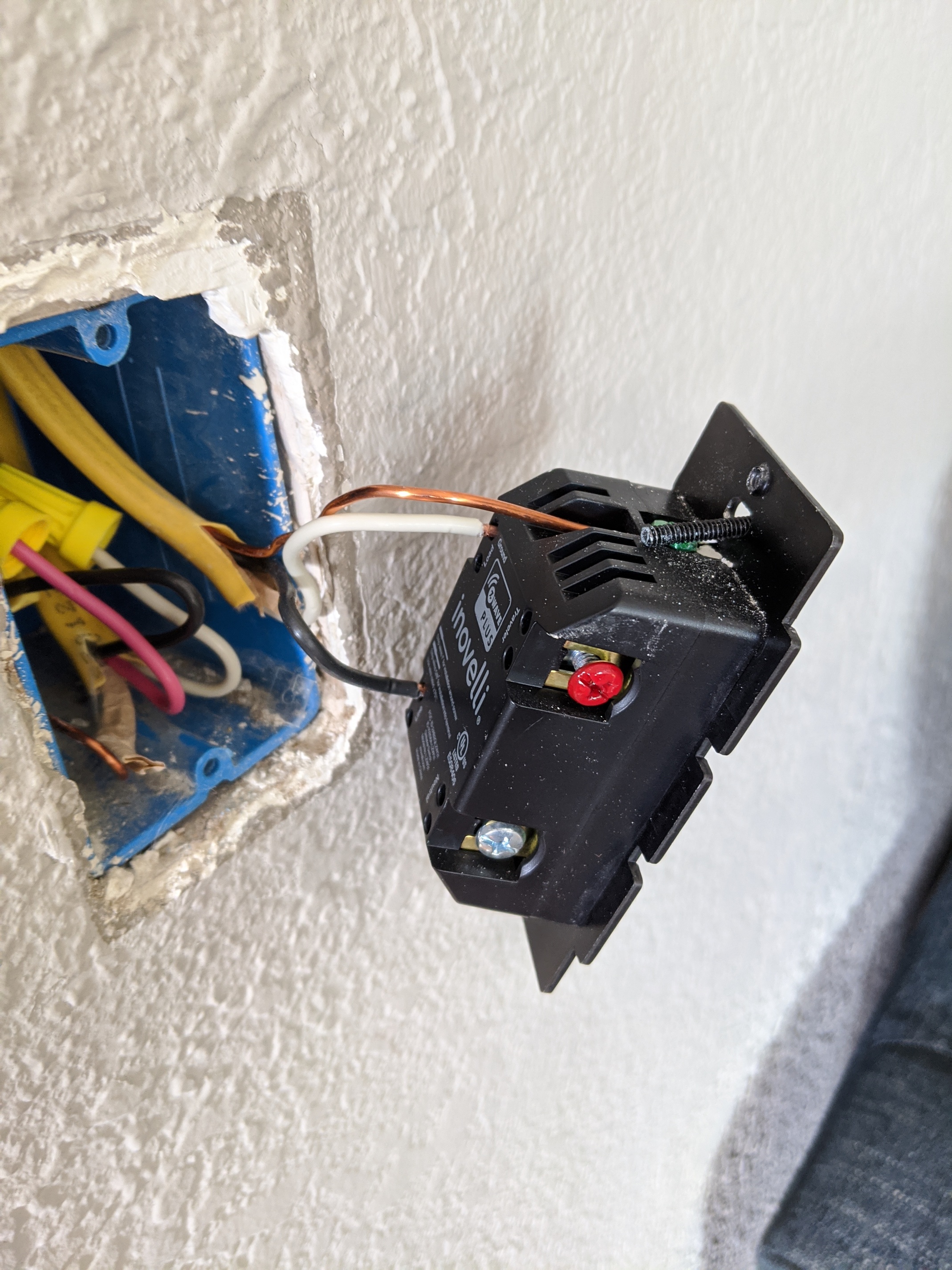
I have the LZW31 black series (non-neutral) and am attempting to add a Jasco 45710 add-on switch. However, the wiring is a little different than my previous experience in newer homes. Current home is a 1903 non-neutral setup in most of the house.
At this time the LZW31 non-neutral is functioning without any issues. Call this the primary. In the primary gang box there is a 4 wire conduit that runs to the secondary gang box. Nothing is connected in the primary gang box.
For the add-on switch, it needs a ground, traveler and neutral. Connecting the red and ground in both to the traveler and ground terminal is straight forward. There is no neutral in the primary gang box. What about the neutral line?
What are the options? Connect the line to the neutral on the add-on?
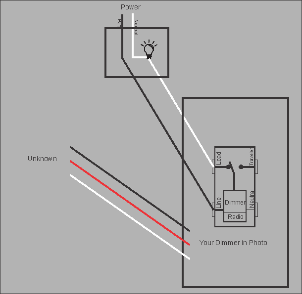
So the current situation is the Inovelli is wired as a “non neutral” dimmer. Likely going to either the other location (where you wish to put an Aux switch) or the load.
In the primary gang box there is a 4 wire conduit that runs to the secondary gang box.
This would be the Yellow “Romex” wire on the left of the photo. The one with all three wires capped off?
So far it looks like this (I think).
Note on the bare (equipment/safety) wire. I don’t show it in my dwgs, however it should be carries throughout the circuit. So if the currently capped wires are used you must connect its bare wire to the bare wire that is connected to the dimmer.
So now where is the Aux going and were are those wires? Can you look at the load (light) wiring and see what is there?
Could the three capped wires be going to your Aux location?
If you are correct the Aux wiring will be easy. But first we need to be sure they are what you think. Do you have a multimeter that you can measure ohms with?
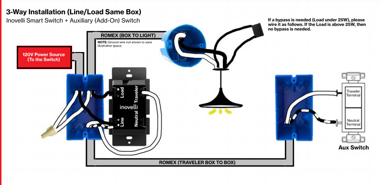
Simply pick the black and white from the 3 wire, connect them between the dimmer line (black) and dimmer traveler (white)
then connect them to the Aux switch.