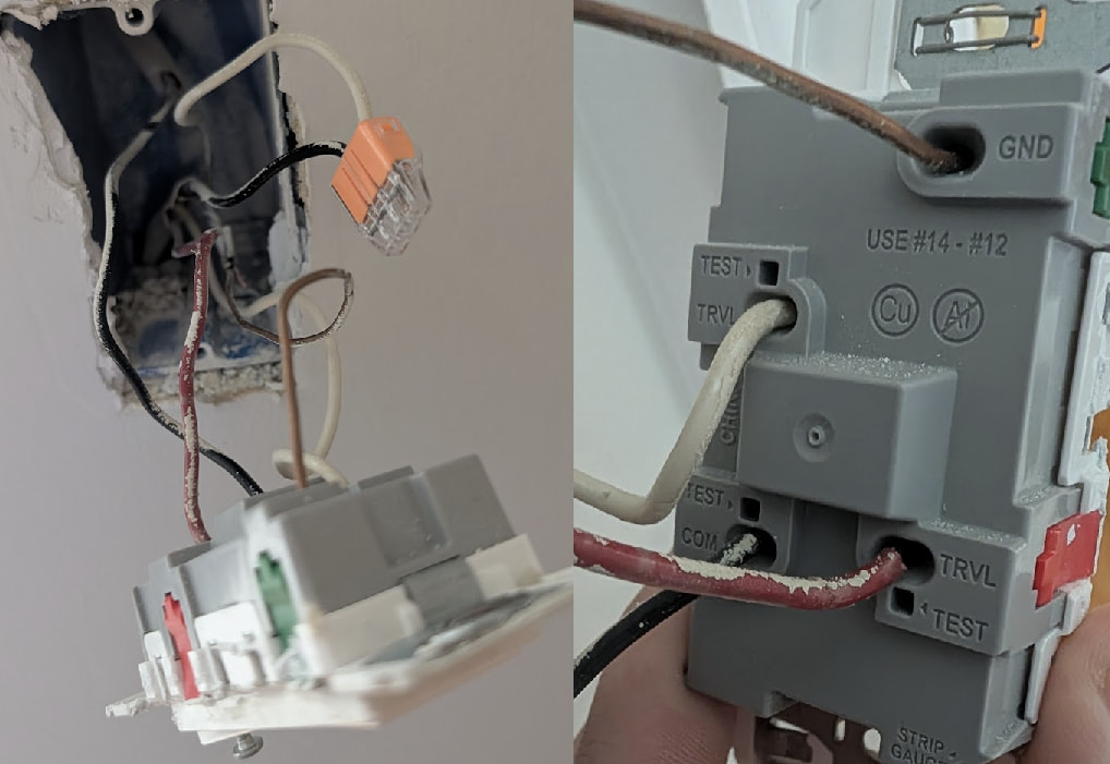
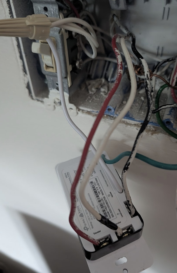
Currently have a three way configuration with a “dumb” switch on one end and a Kasa HS210 WiFi switch on the other. Looking to replace both with Inovelli Blue. They are located at the top and bottom of a stairwell, and control two overhead lights at opposite ends of the stairs. The switches will be configured in smart bulb mode - the lights are Hue and need constant power.
Looking at the wiring diagrams, I believe I may need to use an Aux switch on one side. However a few notes:
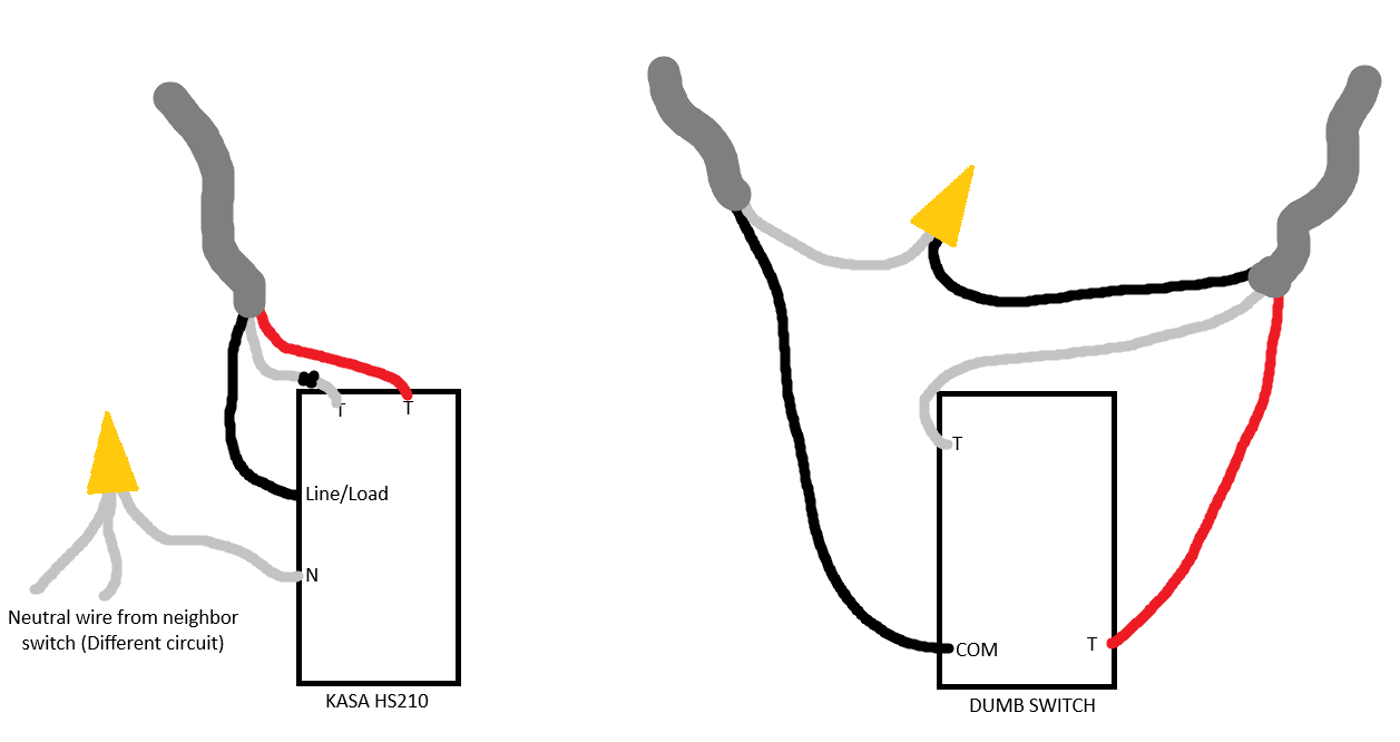
The side that appears to be a dead-end three-way is in a 3-gang box that shares neighbors with other circuits, complete with neutrals. The current WiFi switch is neutral connected there.
The opposite switch does not have a neutral bundle, but has a three-wire romex coming into the box and a two-wire romex into the box
I believe that this may require an aux switch. Ideally I’d like to have full VZM31SN’s on both if that’s doable utilizing the “stolen neutral”.
Alternatively, I am fine with a wiring solution that provides power to both switches and constant power to the lights, and utilizing the switches in ‘smart-bulb mode’ to turn control the Hue’s state via Zigbee instead of physically controlling the circuit via the switch.
So, your switch circuit is on a switch loop, and have incorrectly used a neutral from a different circuit to get your Kasa switch working.
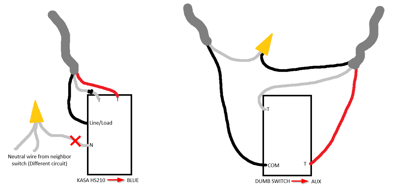
You WILL need an Aux switch and not use the neutral that the Kasa switch is currently using. The good news is that you can put the Inovelli Dimmer in either box though. Decide which box you would like it in and I will attempt to give you instructions and a diagram that you can follow to get it all wired up.
Greatly appreciate the assist! Aux would probably work best to replace the “dumb switch” that’s currently in place. Definitely will remove the neutral.
Well, it wouldn’t only “work best”, but as the circuit doesn’t have a neutral it is required, as a dumb 3-way isn’t supported for a non neutral connection.
One other thing to keep in mind is that when hooked up in a non neutral connection is that depending on the size of the load on the switch, you may need a bypass to allow the switch to get enough current.
If there are only a couple of low wattage LED bulbs on the switch, then this is likely needed, but if it is connected to a larger amount of lights, or the lights are using higher wattage incandescent bulbs, then a bypass may not be needed.
I think the “rule of thumb” here is about 25w of load or so… more than that and you’ll likely be ok, but less than that and you will almost certainly need the bypass.
The bypass gets installed in one of the lights between the switchleg and neutral.
Bypass and aux switch deliver today, so I’m going to try and get this wired up.
@koadic, you had said that you thought I could place the aux on either side of this. I’d like to replace the Kasa HS210 with the Blue switch (non-neutral mode, obviously) and the dumb switch with the aux, but I can’t figure out what the wiring there would look like as the config I currently have doesn’t seem to line up with the wiring diagrams provided in the support docs.
Would you be able to walk through how to change the wiring to support the following? If putting the aux on the right side doesn’t work, using it on the left side is fine too.
Thanks again, I really appreciate all of your help!
Sure, I will also try and create a bit of a diagram and either add it after this via edit or just in another reply.
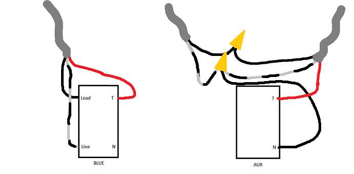
Currently your Line/power is coming into the box with the dumb switch on the white wire from the 2 wire cable, while that black wire is your Load. In that box, to try to make it a bit easier on the next person who has to mess with the switches, even if that is you, we will want to make a couple changes.
After you have turned off power for that circuit and removed both switches, in the box where your power comes in, disconnect the black and white wires from each other. Connect both black wires together, as these will be the Load wire and will not connect to the aux switch. Next, you will want to mark both the white wires in that box with black tape or a black sharpie to indicate that they are not neutral wires, then connect both wires together while also adding a pigtail for the aux switch, as this will be your Line wire and will connect to the Neutral terminal on the switch (lol, confusing isn’t it). The remaining red wire will be your Traveler between the dimmer and aux switch.
At the box that held the Kasa switch, make sure that white wire is also marked with black tape or a sharpie to indicate it is not a neutral wire. That “white” wire will be your Line, the black wire will be your Load, and the red wire will be your Traveler, leaving the Neutral terminal empty.
Finally, at one of the lights, you will install the bypass between the switched black hot wire and the white neutral wire.
Thank you so much for this write-up, it makes everything so much clearer. I’ll get this done later today and let you know if I have any issues (I doubt I will).