My writing setup doesn’t seem to match the Inovelli “before” diagram for this situation so I’m unsure how to wire the new switches.
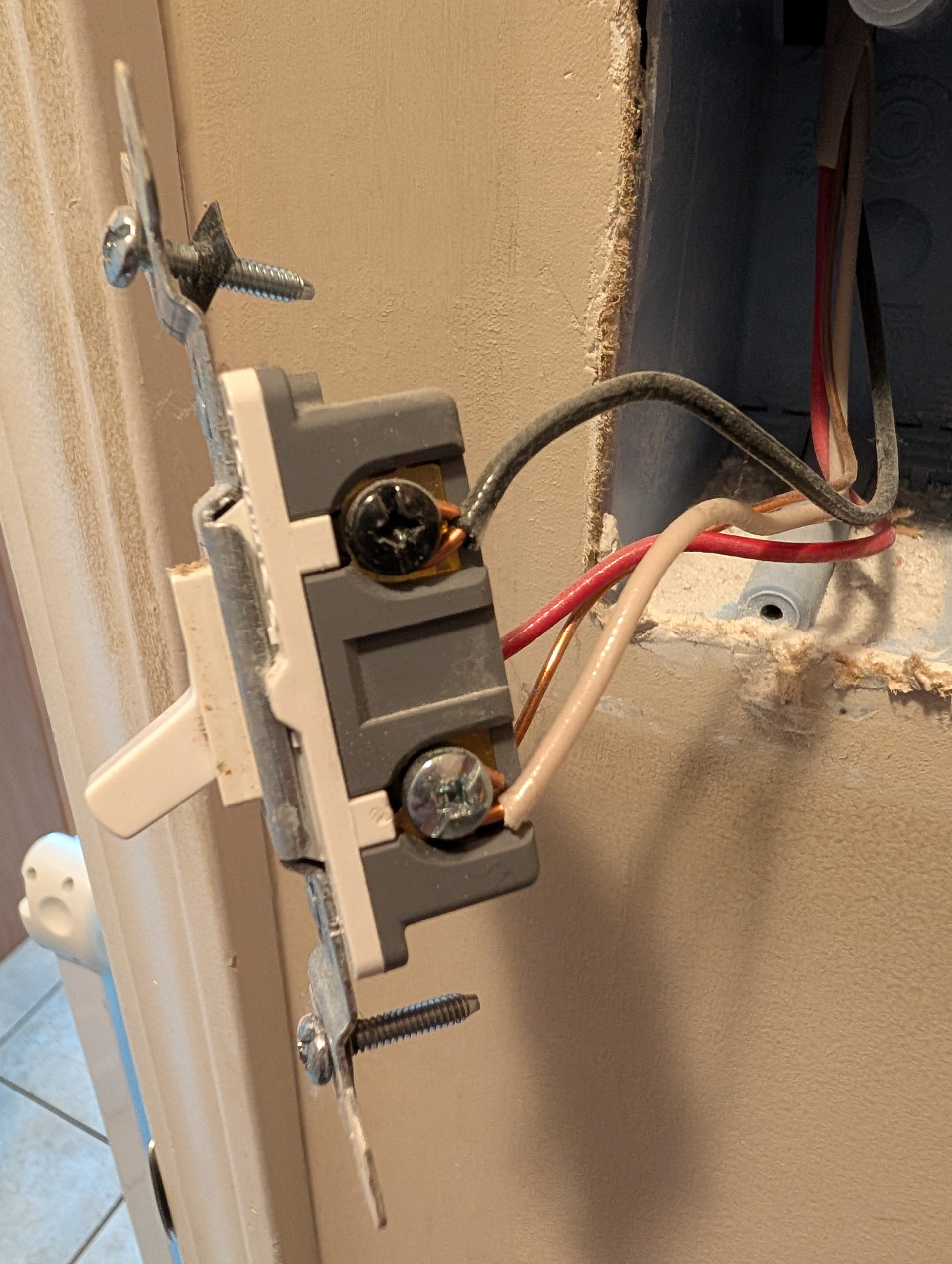
Switch/box #1 has a black wire which is the LINE, connected to the black screw on the switch. Also, a red and a white line connected to the silver screws on the switch which I believe are travelers. And a bare ground wire.
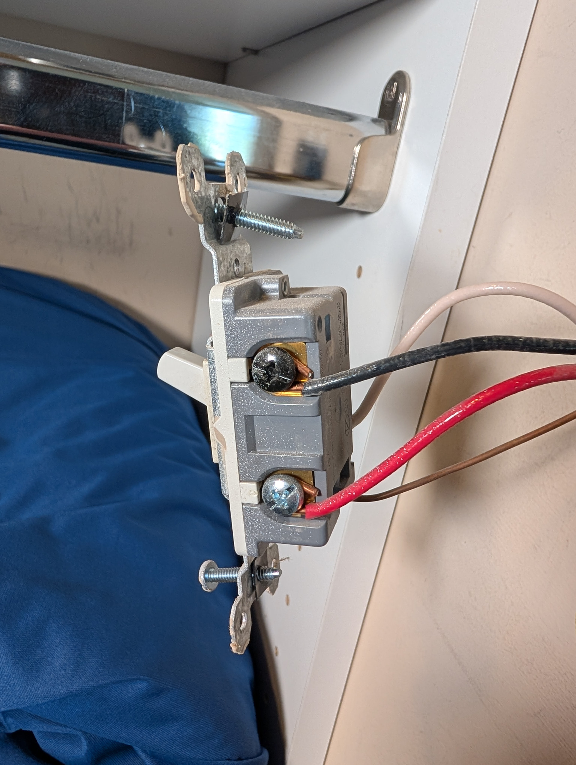
Switch/box #2 has a black wire (LOAD?) connected to the black screw on the switch. Also a red and a white wire connected to the silver screws on the switch. And a bare ground wire.
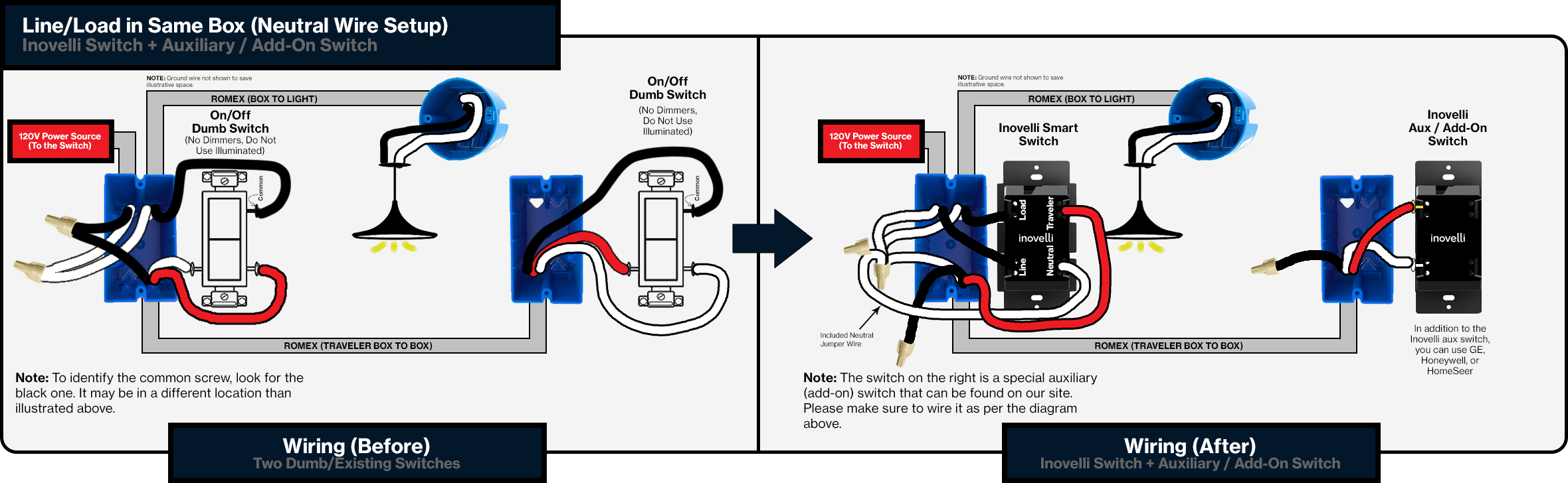
The Inovelli diagram seems to show both line and load connecting to the Inovelli switch, but I don’t believe I have both line and load coming into box #1. I’m clearly confused and don’t know where to begin.
I can see in the first photo that there is only a single romex in the box, that would make this a “dead end 3-way”, and your line and load will be in the other box… unless it is fed from a box central to both of these.
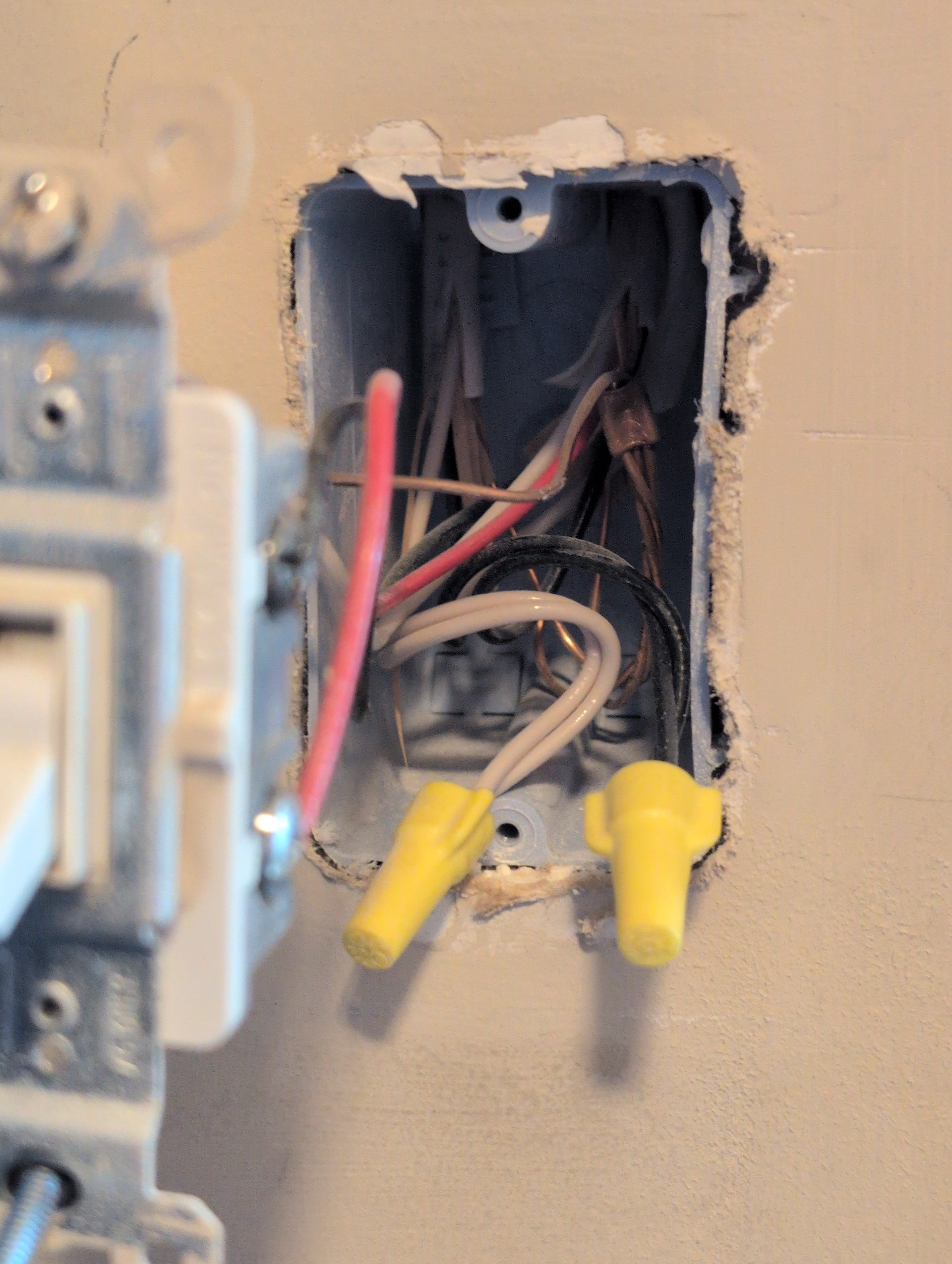
Get a photo of the interior of the second box and post it here.
Doing as you described, the black wire connected to the switch reads zero. Checking the two black wires in the wire nut, one of those reads zero and the other reads 120v.
Ok, the one that reads 120v is your Line, while the black that is currently connected to that switch is your Load.
You will end up abandoning the black wire in the 3-wire cable going to the other switch, and will only use the red and white. You will also need to tie the white wire into the other white wires in that box. The red wire will be the Traveler that goes between the two switches.
Ok, this sounds simple enough. Thank you for helping me sort out my existing wiring and how to proceed. I clearly wasn’t figuring it out on my own. I will work on this and hope it goes as intended.