Trying to wire 2 smart dimmers in a 3 way setting, but the existing 3 way dumb switches doesn’t follow any of the diagrams in the docs Blue Series 2-1 Switch • Wiring Schematics | Inovelli Help Center
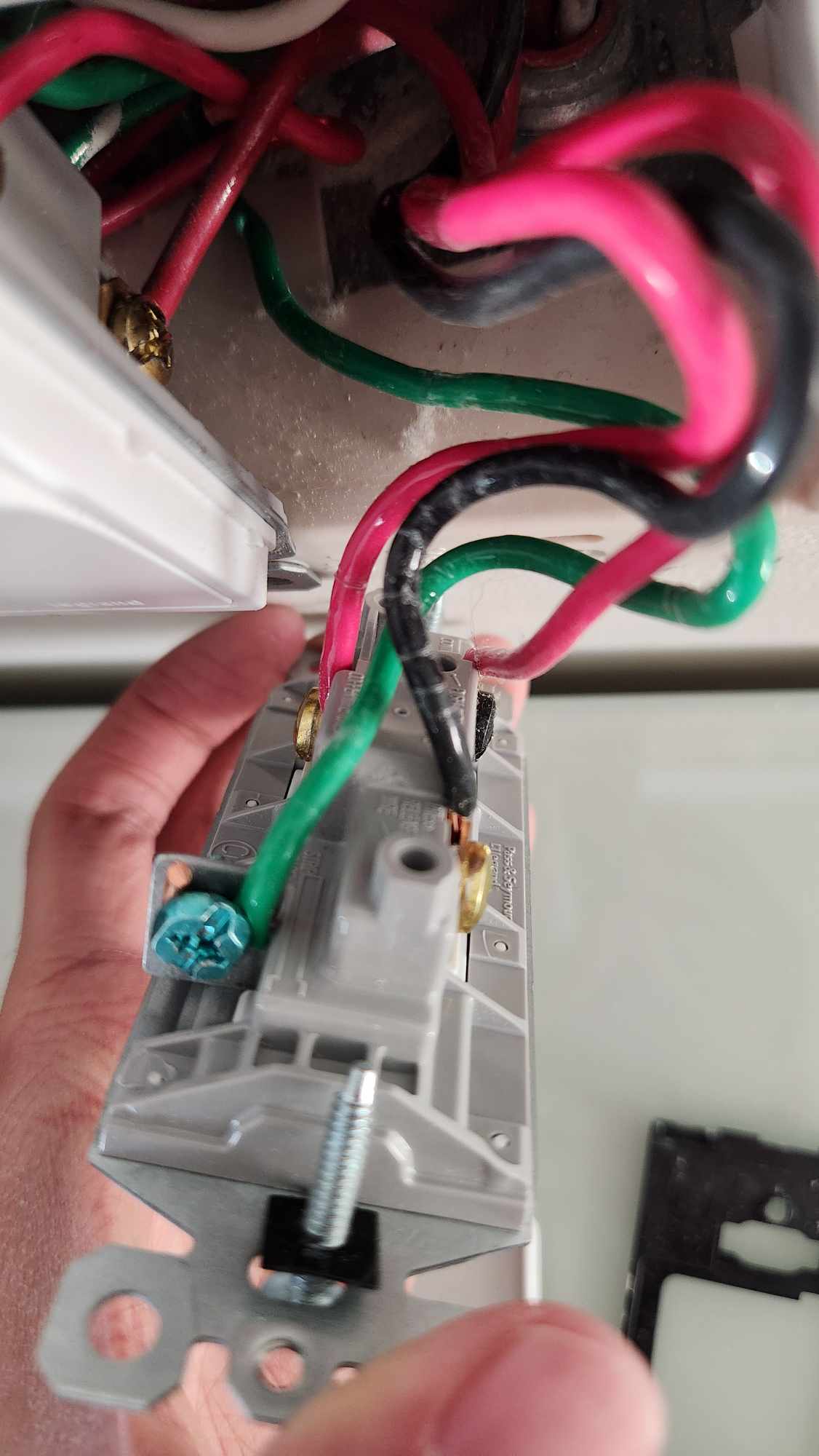
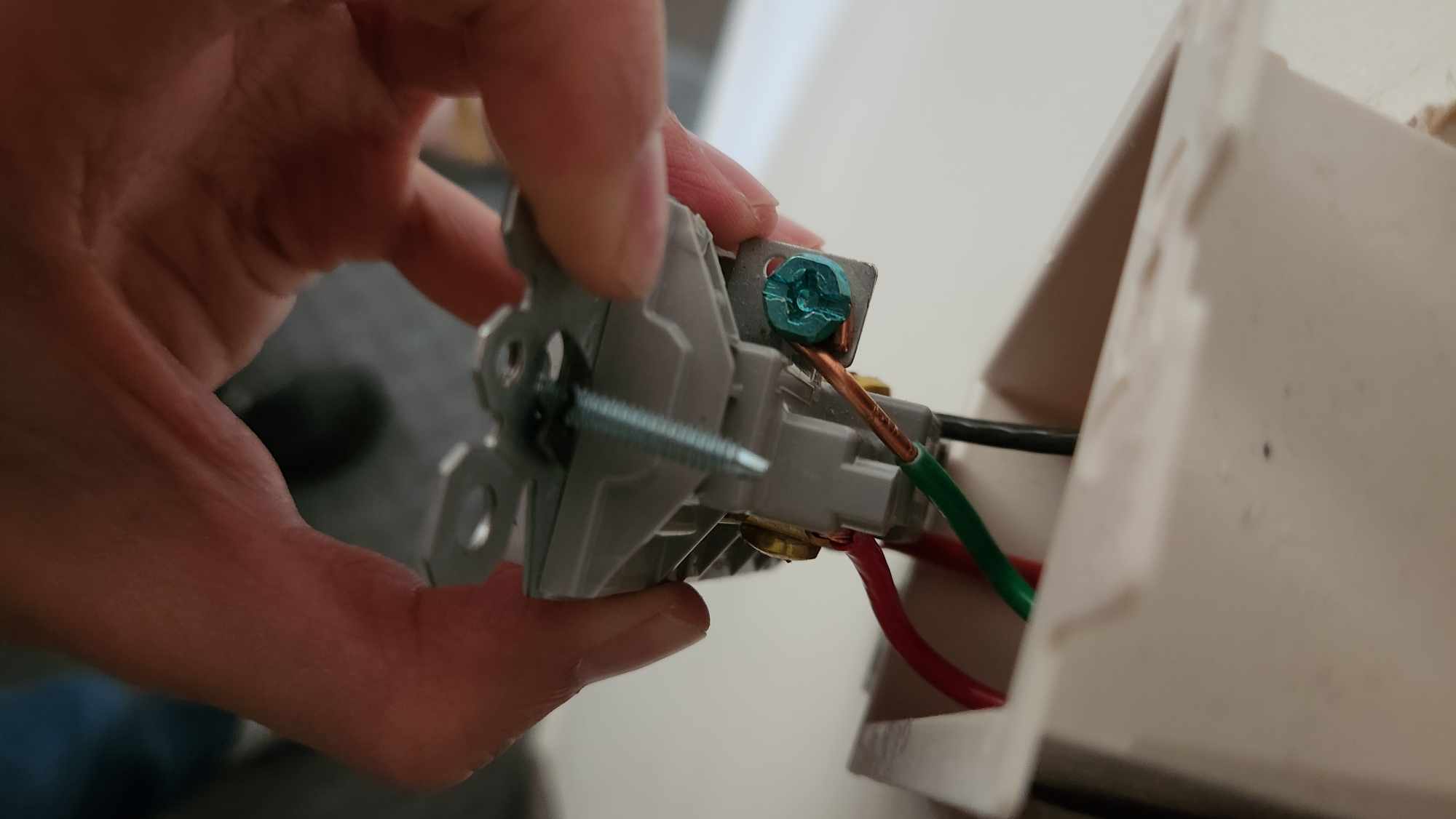
My existing switches are legrand radiant 3 way switches, so they actually have 4 wires connected to them. None of the 4 wires connected are white (neutral), but there is a white wire in the box.
Attached are photos of the existing wiring.
And here’s the doc for them Document
But also slightly confused because the actual wiring doesn’t match the installation sheet (one of the black is swapped with the red)
It’s not a good idea to rely on wire colors alone. You want to know exactly what is wired where.
The LeGrande diagram is only showing the setup for the basic line and load in different boxes. It’s not the only way they can be wired.
I suggest grabbing that multimeter and testing the voltage of each of the 3 terminals on each switch, in all 4 switch position combinations (Up/Up, Up/Down, Down/Up, Down/Down) along with the light state. Don’t simply use a non-contact voltage tester: It’s likely you will encounter induced voltage readings on the inactive travelers, and that will still trigger a non-contact voltage tester, so you’ll want the exact readouts from the multimeter. So you might see something like 45V or 65V in these situations.
Once you do this it should become obvious how it’s wired.
Is there a way I can safely test via trials to figure out how to properly wire the innovelli switches in?
I don’t think I’m comfortable testing live voltages, but would be happy to try different wire configurations and observing the light/switch behaviours to figure out how to put the innovellis in.