The configuration generally works, but the aux switch cannot turn the light on. If already on the aux switch can be used to turn off the light, but not on. Is this a result of having the line voltage at the neutral connection on the aux switch? Is there another way to make this arrangement work?
By the way, I don’t see this configuration in the supplied wiring diagrams, but understand it to be a common wiring for older homes.
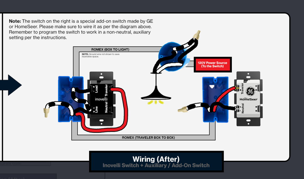
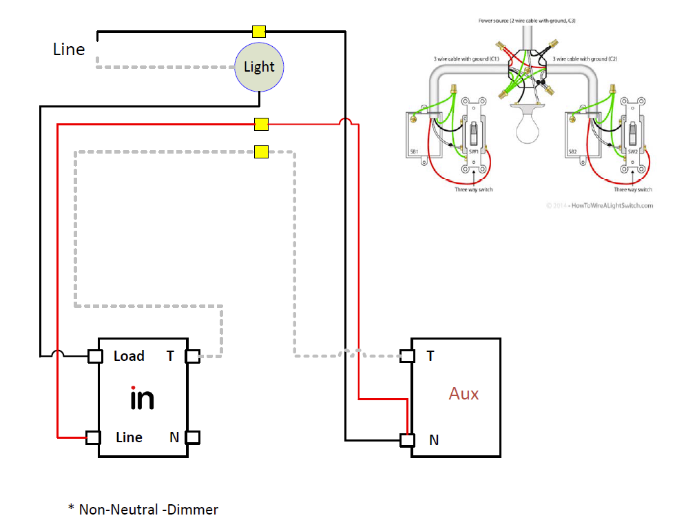
At the Inovelli box, the hot from the light (which is probably coming in over a white conductor) goes to the Line one the Inovelli. The other conductor to/from the light goes to the Load on the Inovelli.
Use one traveler to send the Line from the 2nd Line backwire hole on the Inovelli to the Neutral on the Aux. Use a 2nd traveler to connect the Traveler terminals on the two switches. Cap off the 3rd unused conductor in both boxes.
I took a 2nd look at your drawing. I noticed you have the Line coming into the Aux box but the load to the light to the Inovelli box. That is confusing. Based on your first drawing showing configuration, both the Line and the Load are coming into the first switch box via a 2-wire.
You should not have a line and load in separate boxes as your title suggests, if your configuration is truly like the first drawing you posted.
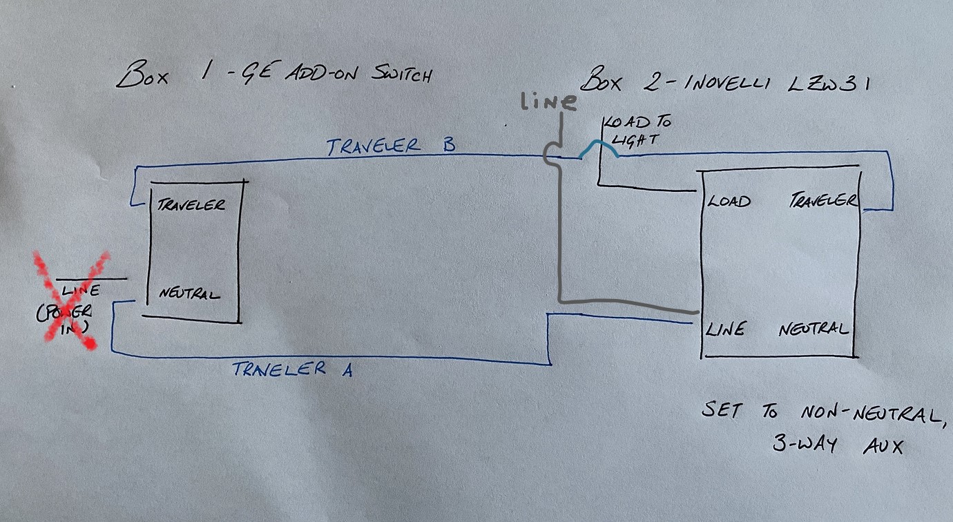
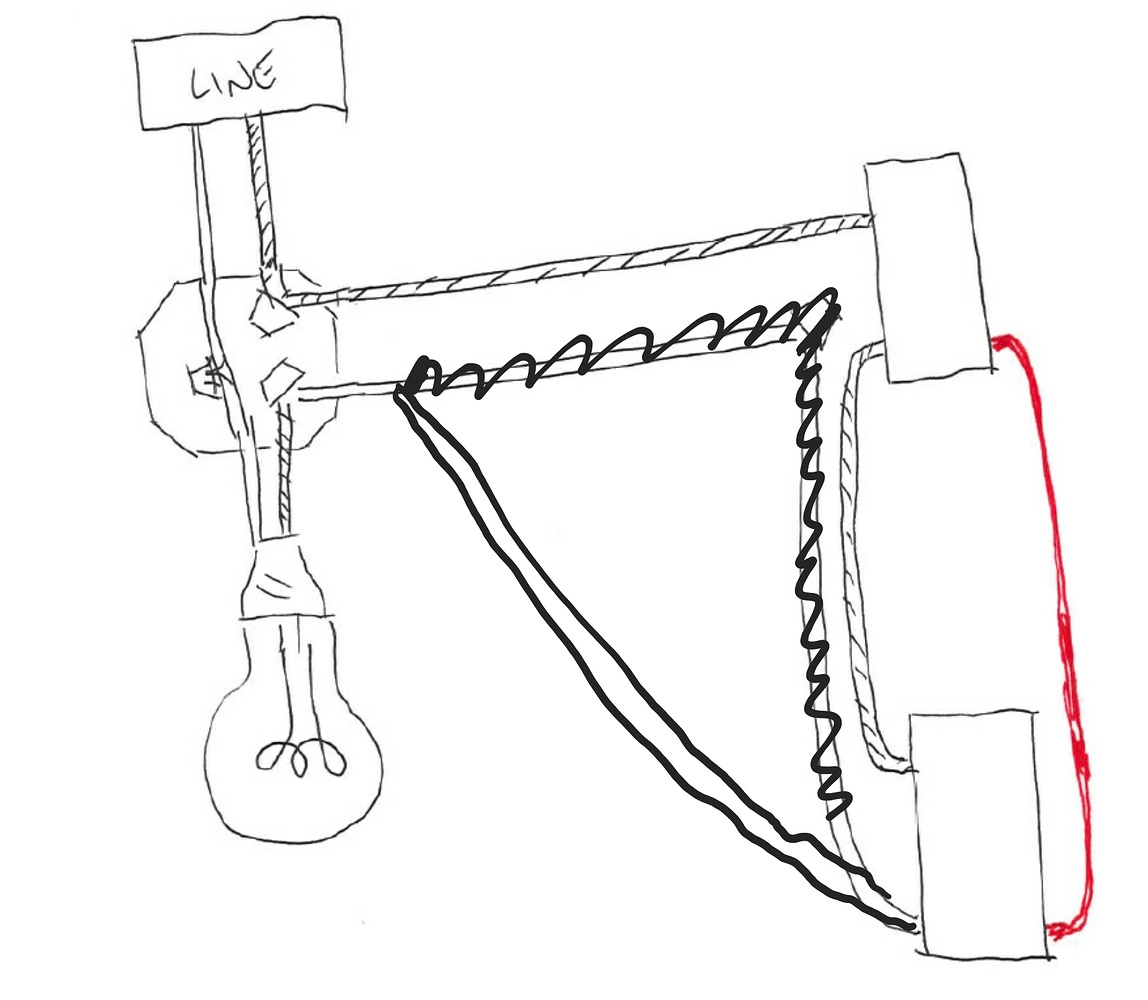
Thanks for the comments. I can appreciate the confusion now. The problem with the suggestions is the wiring diagrams have the load at the same box as the line, which does not seem to be the case. Revising the first drawing to be more clear is this:
Box 1 has three wires : line from the light and two travelers.
Box 2 has three wires : load to the light and two travelers
It seems one option is to jumper a traveler to the load in box 2 and put the smart switch in box 1 without a three way capability. Hopefully with your help I’m missing something and can work out a working three way.
I know you have an old house. So do you have cables coming into the box that are wrapped, similar to today’s Romex? So if I say 2-wire or 3-wire does that make sense? (Don’t count the ground in the wire count.)
It sounds like you are saying that in each switch box you have one 3-wire with ALL THREE CONDUCTORS FROM THE SAME CABLE attached to the switches?
They are not modern romex. They are three separate wires, each wrapped in braided cloth. No ground present. So I don’t think the terms 2-wire and 3-wire apply.
Ok, understood. Let me ask it this way. Are you thinking that all three conductors to each box are coming from the light with power going to the light first. There is a way to test this so we can go through that if need be.
If there are ONLY 3 conductors in each box, ALL attached to the switch, then this may be the case.
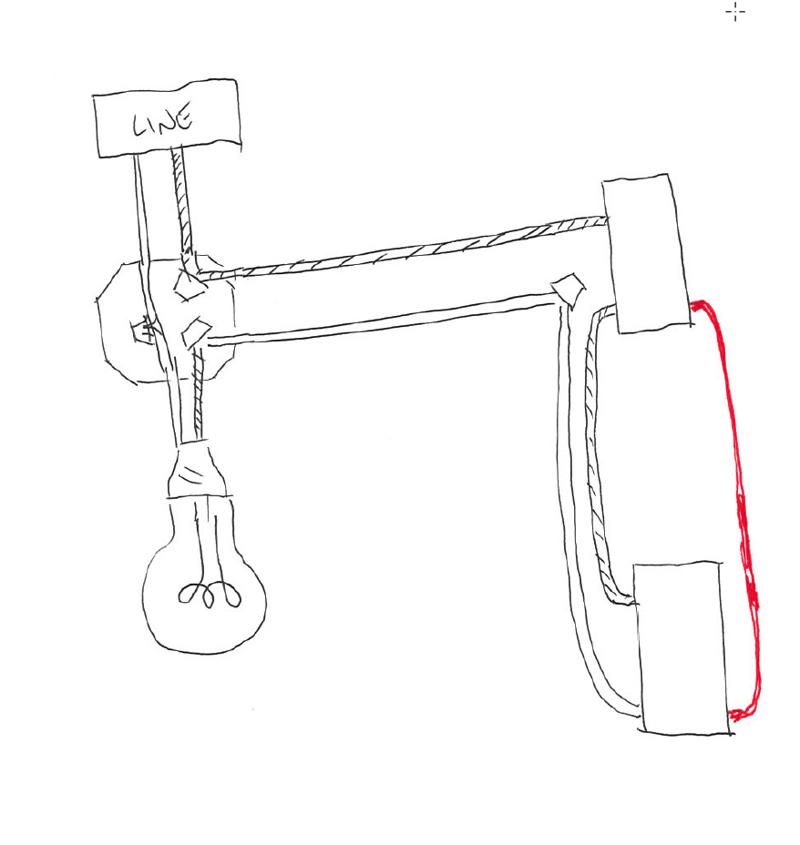
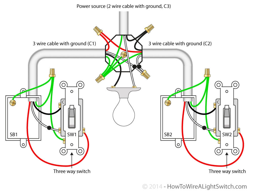
I’m leaning toward power to the light with three conductors going separately to the switch, like this:
That looks like it matches the drawing I pasted earlier (without the grounds and with the labels 1 and 2 switched from mine). I don’t know if the white-with-black-dot and red tied together at the light are truly running back to the light (versus straight between boxes), but electrically speaking seems irrelevant since they are otherwise not connected to anything at the light. Is there a working arrangement for the red series dimmer and a ge aux switch in this configuration?
That matches the setup I am using now, which suggests I am on the right track, thanks. But, the aux switch is only working to turn off the light. If the light is off, the aux switch is not turning it on, although the inovelli switch can. Any thoughts on that? I confirmed the parameters for non neutral and momentary 3 way on the inovelli switch.
What is the load? If it is LED and changeable, temporarily try an incandescent to see if that gets it working properly.
You can try changing the settings to something incorrect and then put them back to the proper settings. I’m referring to the parameters for neutral / non-neutral and the 3-way toggle/momentary. Try from either your hub or at the switch.
You can also try an incorrect setting.
This is not an uncommon problem with a non - neutral. The last person that posted about this issue determined that his switches worked correctly when he temporarily switched to an incandescent bulb.
I know you said that the drawing I posted matches how you have it wired, but you also posted a revised drawing. Your revised drawing doesn’t match our solution, so if your actual configuration matches your revised drawing, I don’t think it’s correct.
I think they are the same, under the assumption that the wire locations relative to the not-shown terminals on the switches in my diagram are not meant to indicate which terminal they connect to. The switches are wired in the manner that matches your more detailed schematic.
The GE add-on is brand new switch out of the box. But if others have confirmed that this wiring that passing the line voltage through the neutral terminal of the add-on switch should work, maybe it is a defective switch?
So maybe it’s just your drawing and not how you have it wired, but there are two things that confuse me on your drawing.
1 - An Aux switch only has 2 terminals. The switches in your drawing both have three so it’s not clear to me which is the Aux, plus one of them has an extra terminal that isn’t really there.
2 - In your drawing, the hot (Line) is only going to one switch, the top one. Properly configured, the Line must be routed to the neutral terminal of the Aux.
Yes, I see your points, which are accurately portrayed in your wiring schematic. But, I confirm that wiring is the setup I currently have wired that is not working.
To point #1, I do have two wires tied to the same terminal on the aux switch.
To point #2, I do have the line voltage running first to the aux neutral terminal, which is also coupled to a traveler to the inovelli switch line terminal at the other electrical box.
I’m about out of suggestions. The last thing I can think of is to check for Line voltage at the Inovelli side (with the conductor removed from the switch) to make sure wires didn’t get remapped at the light. I’d also check for continuity on both ends of the traveler conductor. If you can get at the light box where the two 3-wire come in, take a look to make sure it’s wired as you think it is.
Beyond that, double check parameters 21 and 21 to insure non-neutral and 3-way momentary.