I do not know the wiring at the fixture unfortunately (besides that one of the leads at the light is 0V referenced to GND, so I believe that is neutral), but can take DMM VAC measurements referenced to ground if anyone would like them. I also believe this wiring is operated in “switch loop” mode as my early measurements show that both the black and white wires on the right switch were 120V and both the black and white wires on the left were ~0V.
I looked through the support documentation and could not find anything that resembles this and I have spent the day looking online (including here) for any help. I would really appreciate any help anyone can provide.
I have a 2-1 Blue Switch and an Aux Switch for this project, please let me know if I need anything else.
If anyone would like any measurements or pictures, please let me know.
(I can retake any measurements if anything doesn’t make sense).
The first step is to identify the primary switch box, which is the one with the conductors coming from the light. What type of wiring do you have? Since it’s an older home, it’s probably not Romex, but possibly the equivalent, fabric-covered conductors?
One of the boxes has five conductors (exclusive of ground, if present) and the other box has three, correct?
The primary box is the one with five. Can you identify the two conductors coming from the light? Using a non-contact tester (as opposed to a meter to reference ground, which may or may not be present or reliable in an older home), find out which of the two conductors coming from the light is hot. If the conductors are black and white, it’s probably the white.
I am not sure, the light is between the two switches, but the white top left +red bottom left + black right bottom (so in the figure, the switch on the right) seems to be the switch between the light and the other switch. I hypothesize this because the other switch (yellow painted wall) seems to be an endpoint in the circuit. I am not sure though.
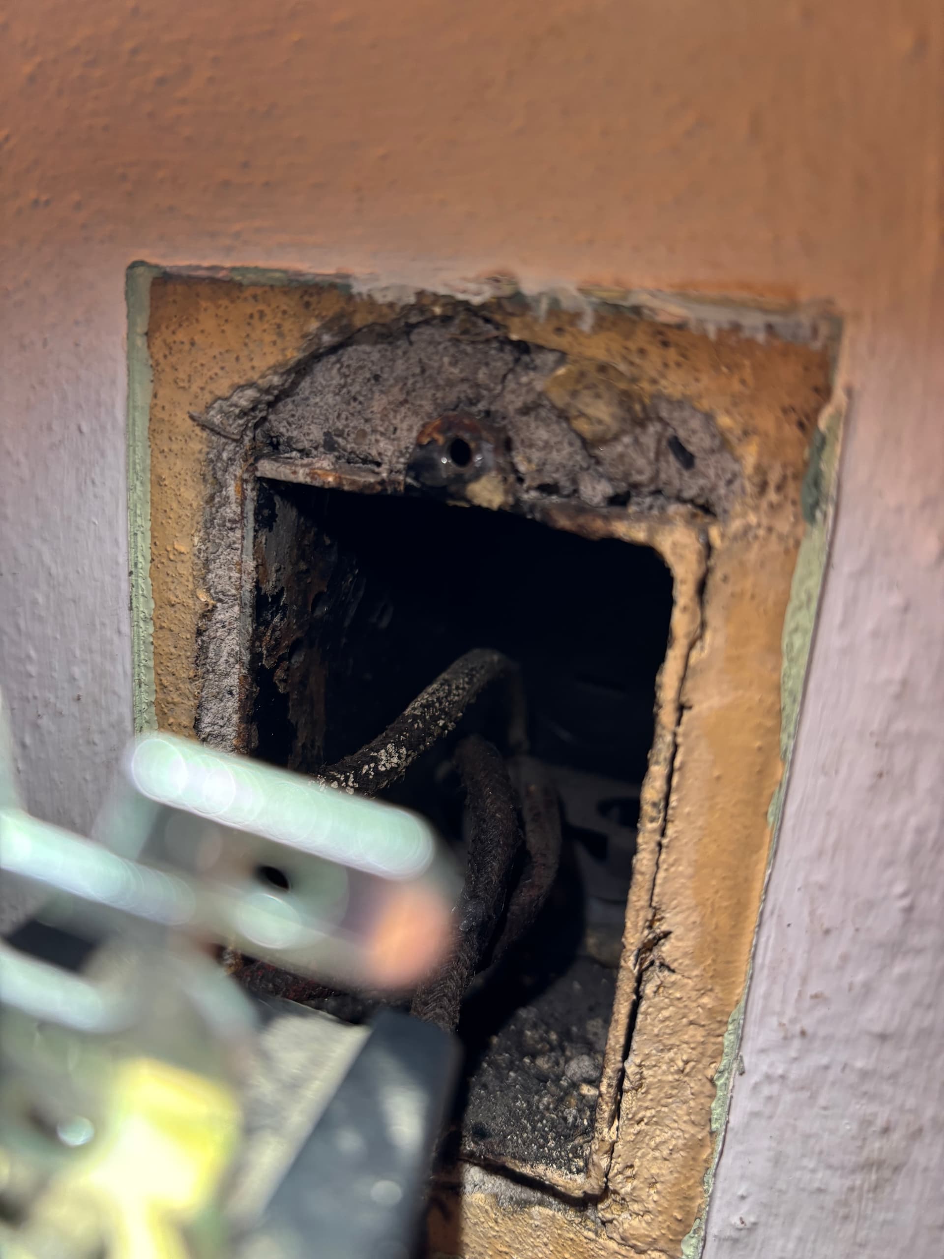
I believe fabric colored. The color is very discolored though
Both boxes have only 3 conductors (additional pics included). I looked into the boxes and tried to capture it in the pictures, but the 3 wires come bundled up in some tubing into the box, and only 3 wires are present.
I will get a non contact tester and report back my results tomorrow. I have a continuity function on my DMM but am not sure if that would suffice
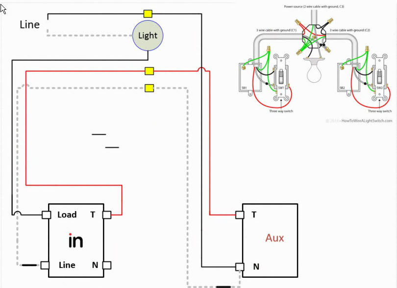
Ok, so if both boxes only have three conductors, that is a totally different wiring topology. The drawing you posted isn’t accurate.
That will still be a non-neutral with power going to the light and then a 3-wire going to each switch box from the light. With the conductors disconnected from the switches, only one of them will be hot. Start by finding that one. Your Aux will go in that box. And you’ll need a dimmer, not an on/off.
Thank you so much! I’ll plan on purchasing a dimmer once I get the chance to check my other multi way switches. Bought a 10 pack of the on/off’s after seeing I had a white wire which turned out to be unfortunate
This wiring configuration works, but only if there is a) a load connected and b) a very light load connected. When I plug in a Phillips Hue bulb, the switch begins to flicker and sometimes restarts.
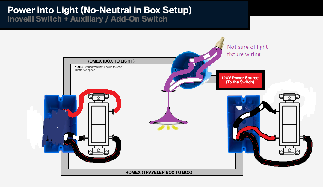
The diagram you provided showing my original wiring is accurate though, and I wired the smart switch (dimmer) and aux exactly as shown.
I did not haha. It’s a ceiling bulb socket. The load should just be the one bulb I am trying to control.
it is an older 1940’s build house though, so honestly I wouldn’t be surprised if this was a receptacle and turned into a sovket over the years (though idk if that would have this affect).
i know the old dumb switches didn’t have any issues so I’m inclined to put those back on and forgo the inovelli route. Any thoughts?
Again thank you for helping me out with my two posts… it’s been quite a day trying to debug these
Yep, I asked about the receptacle because you asked about if the load had to be plugged in, which would indicate a receptacle, as opposed to screwed in, which would indicate a bulb.
Yes, the bulb has to be screwed in with a non-neutral as power needs to pass through it to get back to the switch.
Ok so I think I figured out a hacked up solution. I put a dumb 13W bulb in and turned on local protection so that it doesn’t turn it on. I’ll wire receptacles to phillips hie bulbs in the ceiling by an extension cord from an outlet and vontrol them wirelessly through HA.
Oddly enough, the switch cannot handle the load of a Hue bulb (7.5W) and will restart and flicker, but can mostly handle the dumb 13W bulb (a little noticeable flickering). Not sure what that is about. Sort of disappointed that the switch can’t handle that load but ig my sub optimal wiring is a contributing factor. I might have been better off getting a shelly relay or something though.
The switch can handle the load just fine. The problem is you don’t have enough load and not enough current is getting back to the switch to keep it fully powered. I would try adding a bypass.
Did some more research and I think you’re right. I’ll looking into getting a bypass and hopefully it gets my setup in working order. Definitely cleaner than running an extension cord.