Hello Inovelli Community,
I’ve recently started installing Inovelli White Series smart switches throughout my home and integrating them with Home Assistant. Overall things are going well, but I’ve run into some wiring challenges and could use some guidance.
I’m wondering whether adding Aux switches would help address these issues. I have a few circuits in particular that appear to have non-standard wiring:
- Kitchen
- Mud Room
- Entrance
- (Potentailly) Basement
I’ve also attached a hand-drawn diagram of the wiring setup, based on my observations of the gang boxes.
The house was built in 2007, so it has relatively modern wiring.
Observed Issues
The primary issue I’m seeing is that when I turn off the lights using the existing “dummy” switches, the smart switch loses power and shuts off completely.
Additionally, when I turn the lights off via Home Assistant or directly from the smart switch, the smart switch appears to power-cycle.
Given the non-standard wiring and the fact that the smart switch is currently installed on the load side, this behavior is somewhat expectedbut I want to confirm the best way to resolve it.
Wiring Details
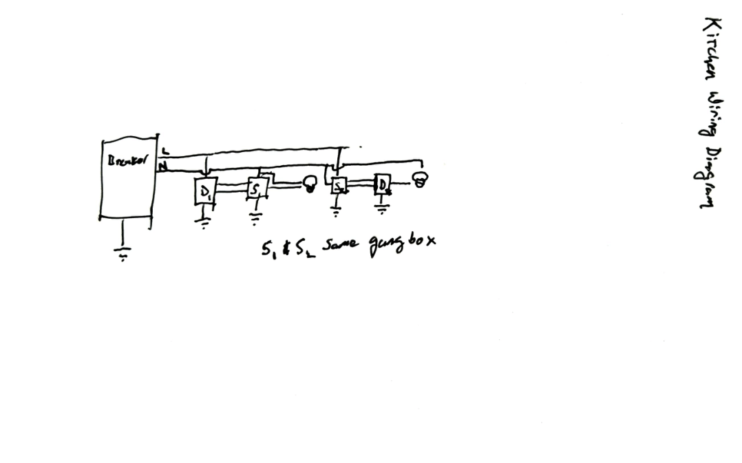
Kitchen
From my inspection, it looks like the line switch doesn’t have a neutral, but there is a neutral present on the load side. Additionally, the load side of my kitchen lights is in the same gang box as the line of dining room lights. (Note: the dining room lights omitted in the diagram.)
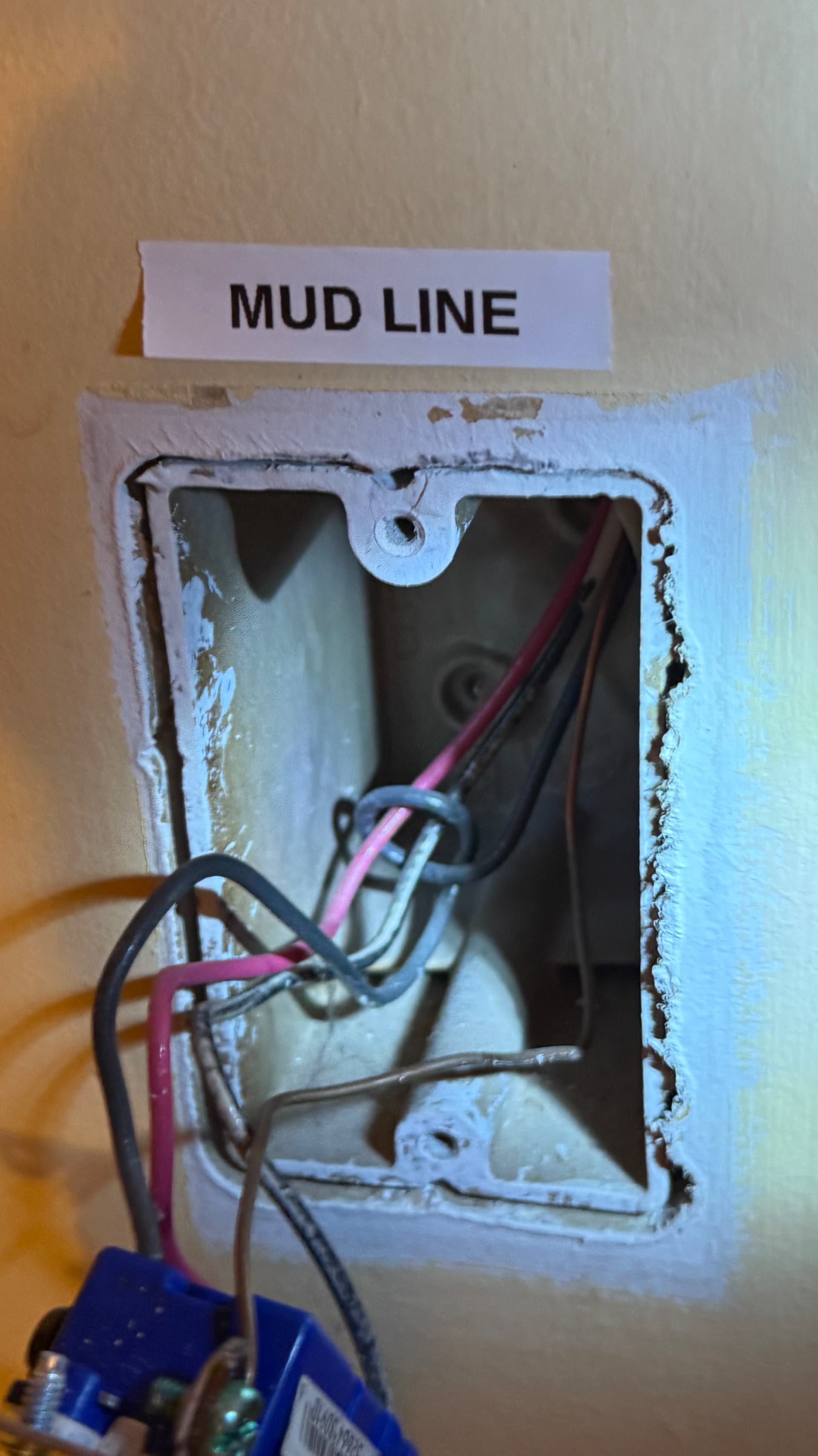
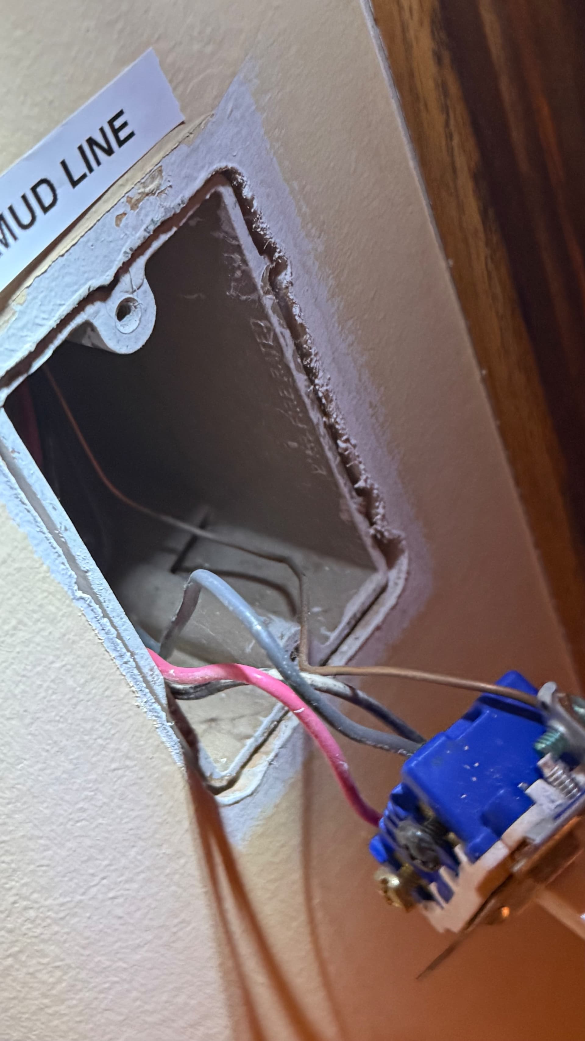
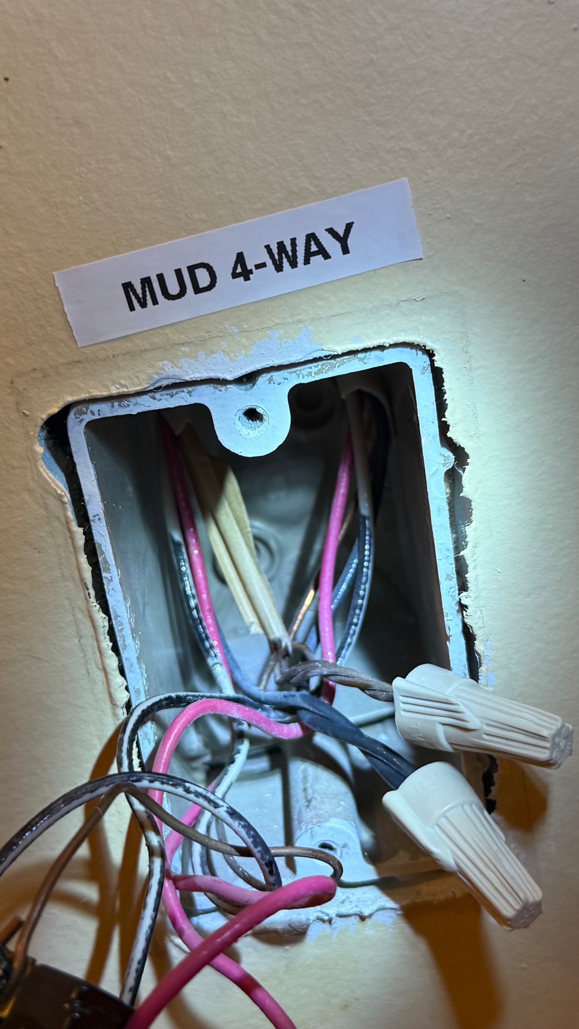
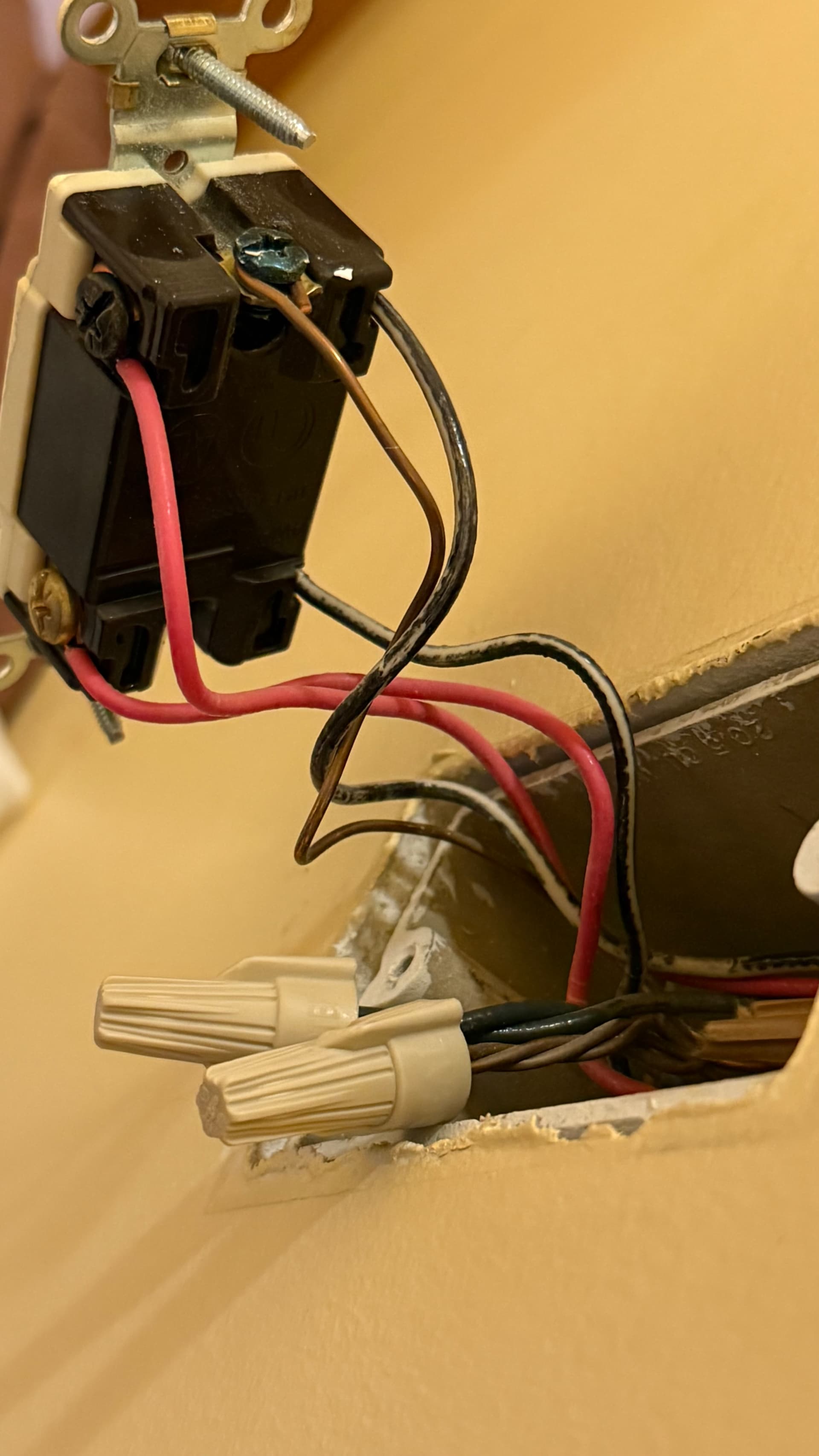
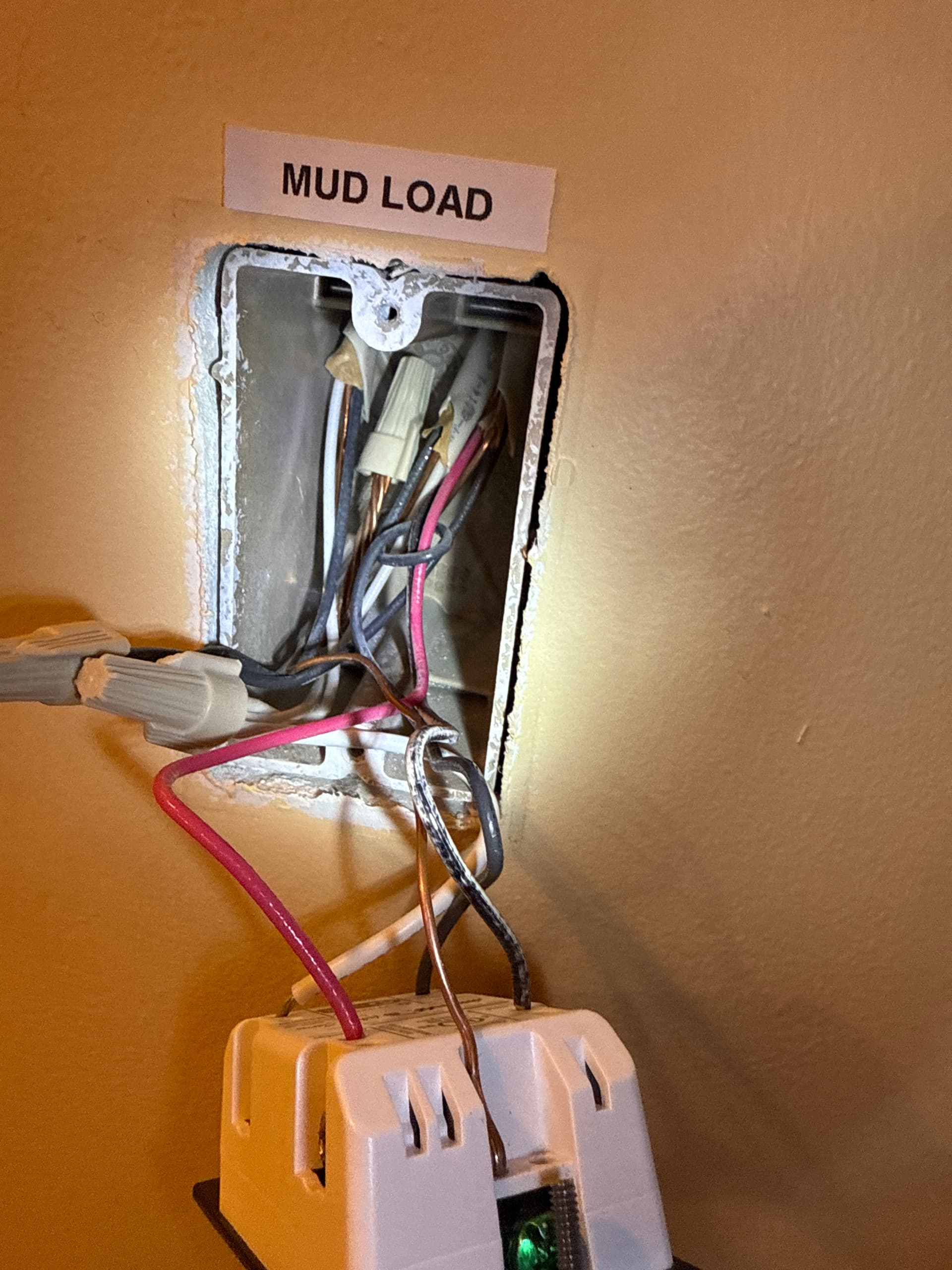
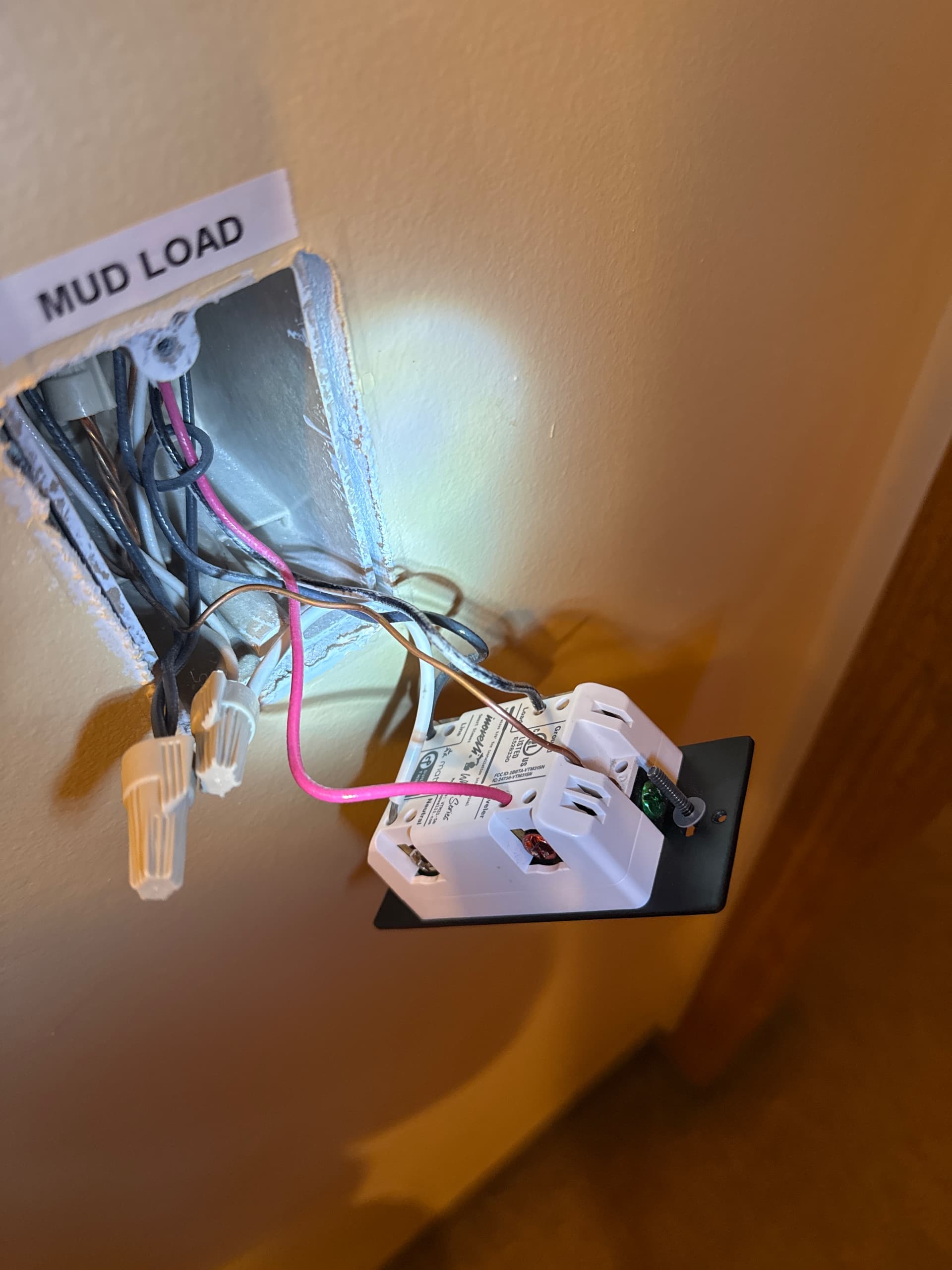
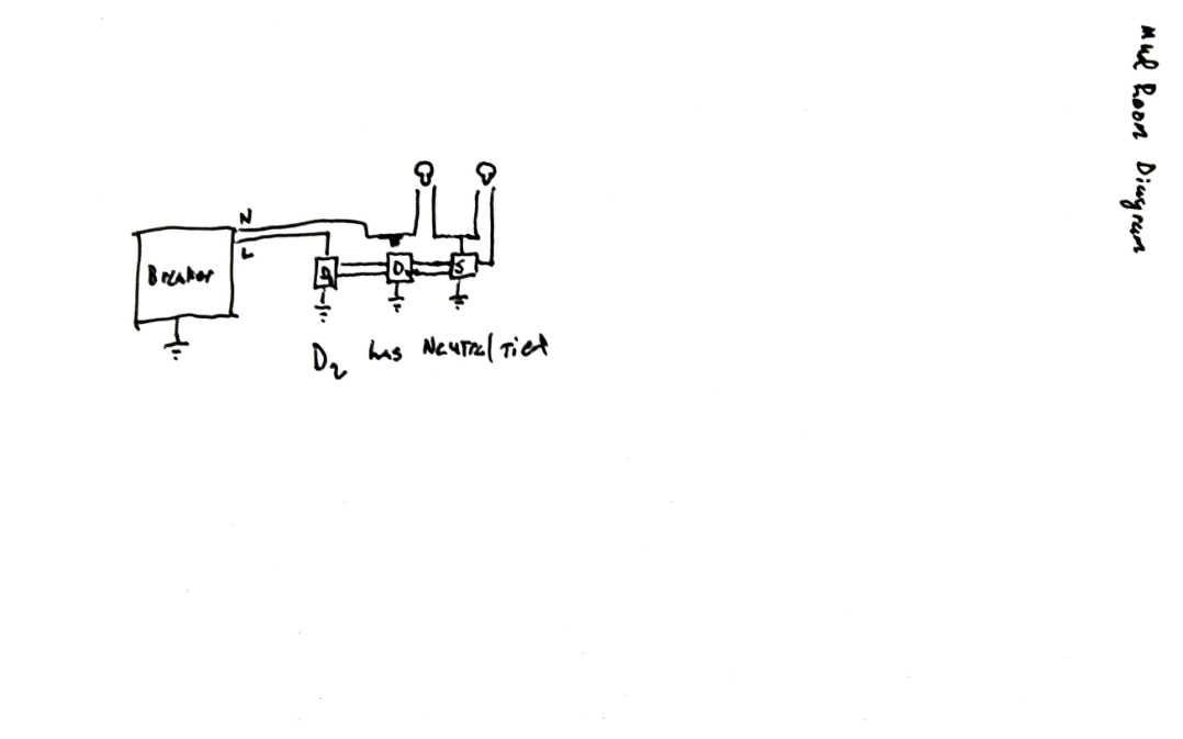
Mud Room
The mud room is wired in a 4-way configuration. Like the kitchen, there is no neutral on the line side, but there is a neutral on the intermediary switch and load side.
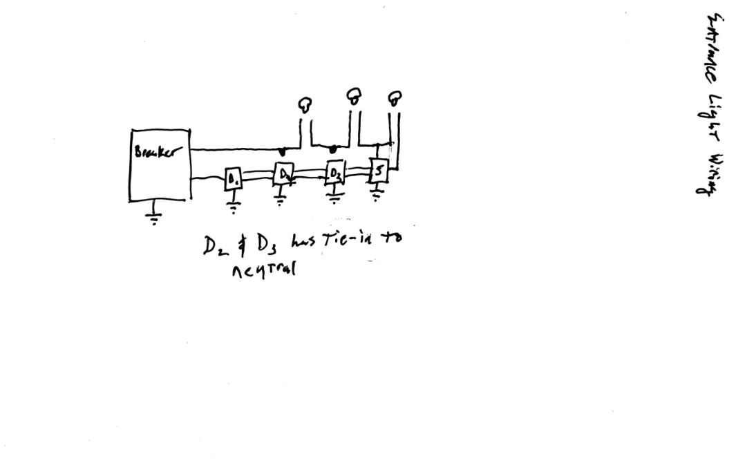
Entrance
The entrance is also a 4-way circuit with four control points:
- Basement (near the stairs)
- Front door
- Bedroom hallway entrance
- Mud room entrance
The line side is located in the basement near the stairs, and the load side is near the bedroom hallway entrance. Like the kitchen and mud room, there is no neutral at the line side, but neutrals are present at the intermediary switches and at the load side.
Additionally, the load side of the entrance circuit is in the same gang box as the line side of my TV lights. The line side of the TV lights is tied to the kitchen circuit breaker. This circuit is also omitted from the diagram.
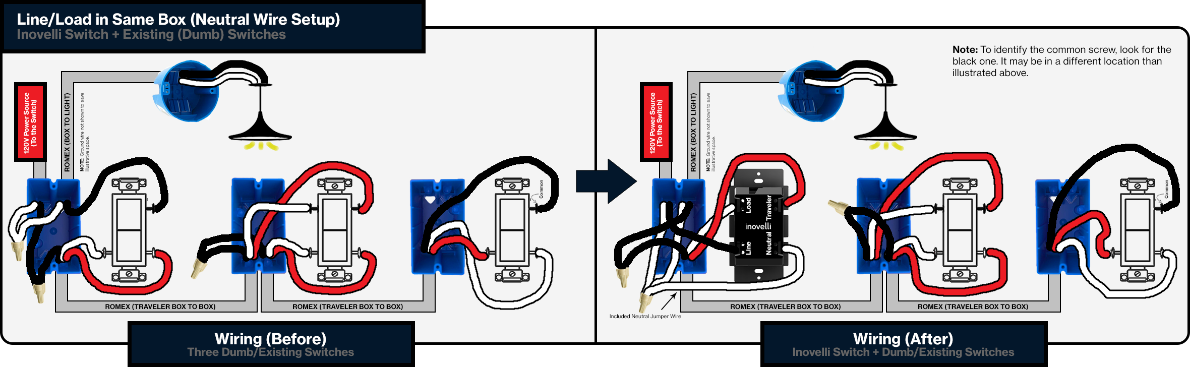
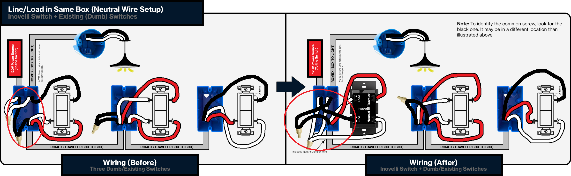
Planned Installation
My current plan is to replace the existing dummy switches with Aux switches, and I’m hoping this will resolve the power-loss and power-cycling issues. I’d appreciate confirmation that this is the correct approach.
Your support is appreciated!