I’m looking for some guidance as to the specific settings I need to adjust in Home Assistant in order to set up 3-way and 4-way switches. I believe I have them wired correctly, but I’m unsure of how to get them to work together.
Is Central Scene my best bet? If yes, do I manage those settings in the ZWave Control Panel, or elsewhere?
Option #2 has below has me completely stumped as far as Home Assistant-specific instructions go.
Ok, thanks to your reply, I found the associations area and sort of have these switches working together. The problem I’m running into is when the main switch is off, the second switch has no power, so is unable to power on the lights. The second switch is able to power off and dim/brighten if the main switch is on.
Thanks for taking a look at this Stu, it’s much appreciated. The problem I’m encountering is that when the power is off, only Switch 1 (leftmost switch in the diagram below) is able to turn the lights on.
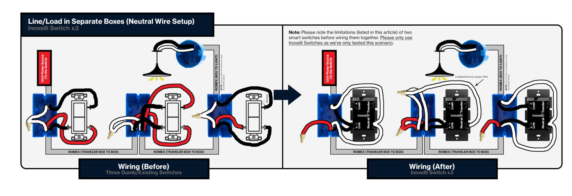
HERE’S THE WIRING DIAGRAM I’M ATTEMPTING TO FOLLOW
Just curious, it doesn’t appear Switch 2 or 3 have anything plugged in to Load? If you’re following the diagram, the last switch in sequence controlling the light is the one that would be connected to Load.
Switch 1 needs to have the wire in the load terminal connected into the line terminal.
Switch 3 needs to have the load wire connected into the load terminal instead of the line terminal. I can’t tell for sure which one it is. Maybe the top wire. It will be the wire that does not go into the 3-conductor romex with the red wire.
Thanks PJF. I set it up as you suggested and got nothing. Switch 1 was no longer controlling the lights. It made me think that perhaps my assumptions are off, and that I cant set up these switches in the way I was hoping.
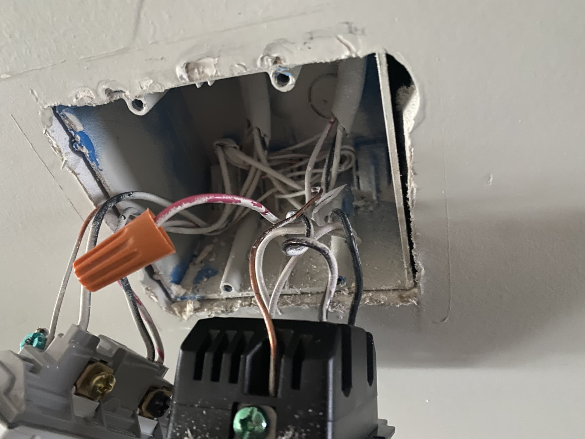
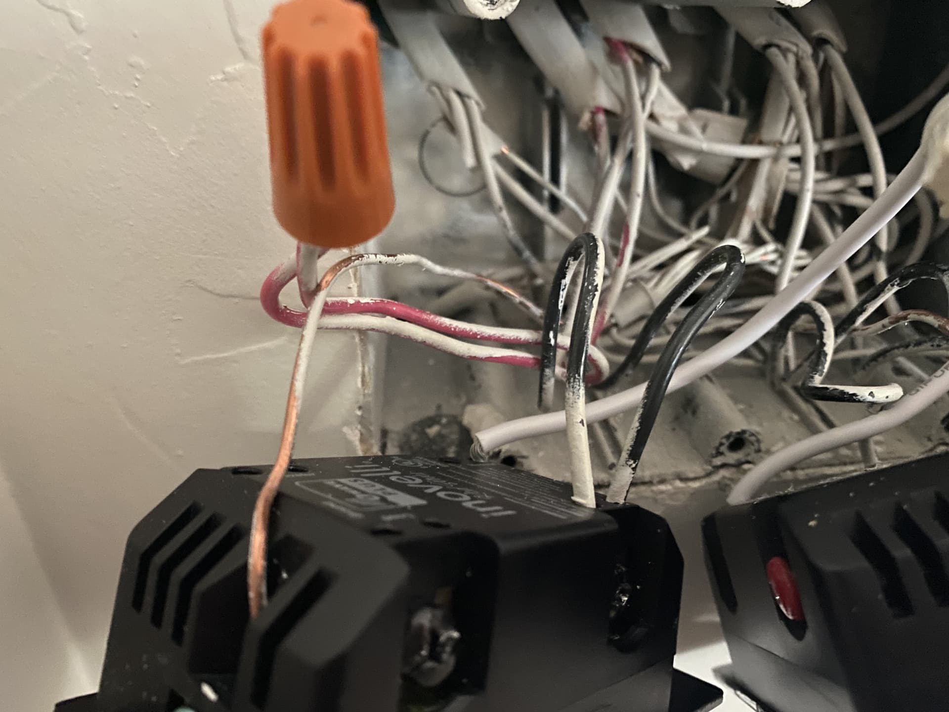
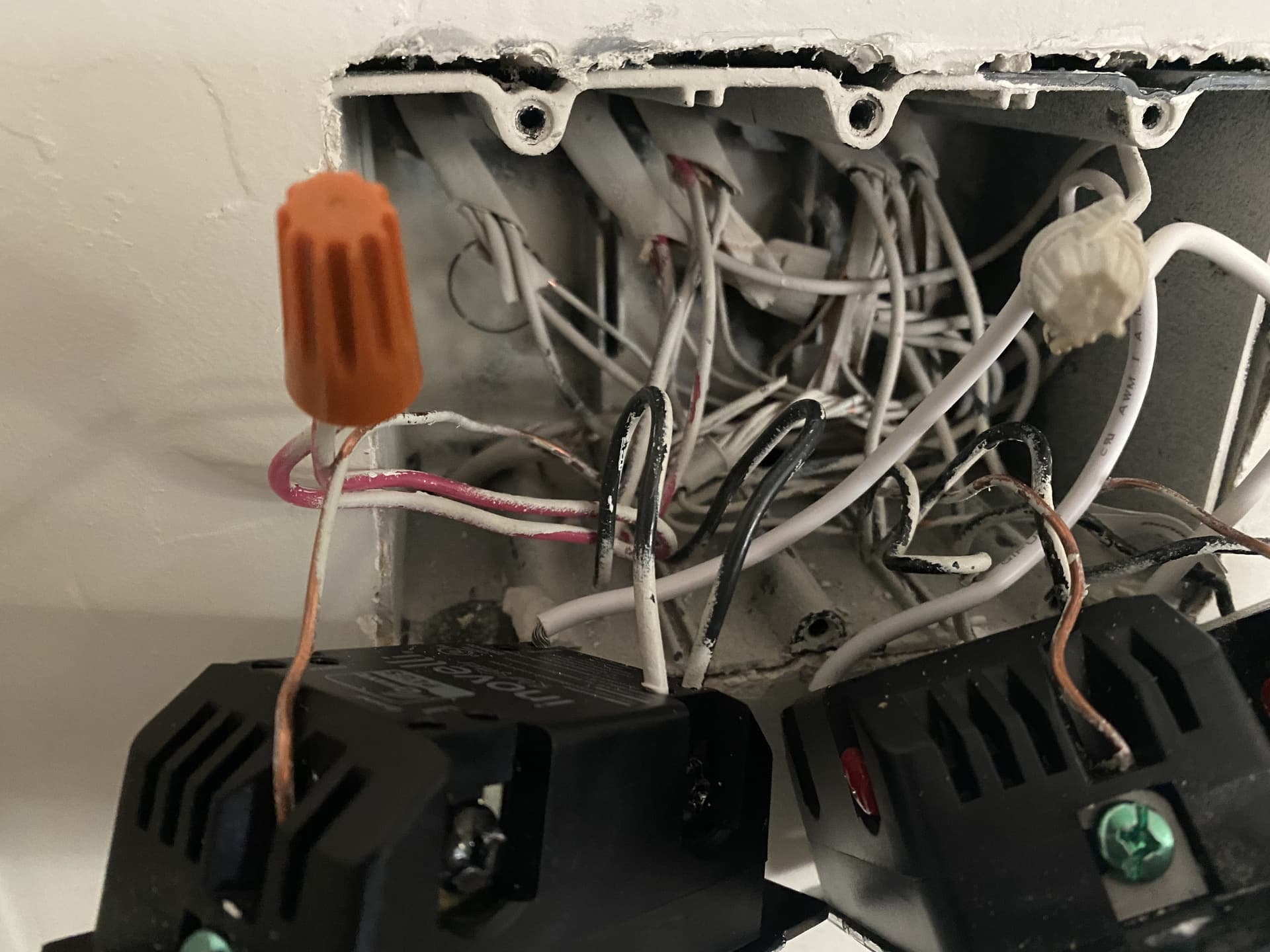
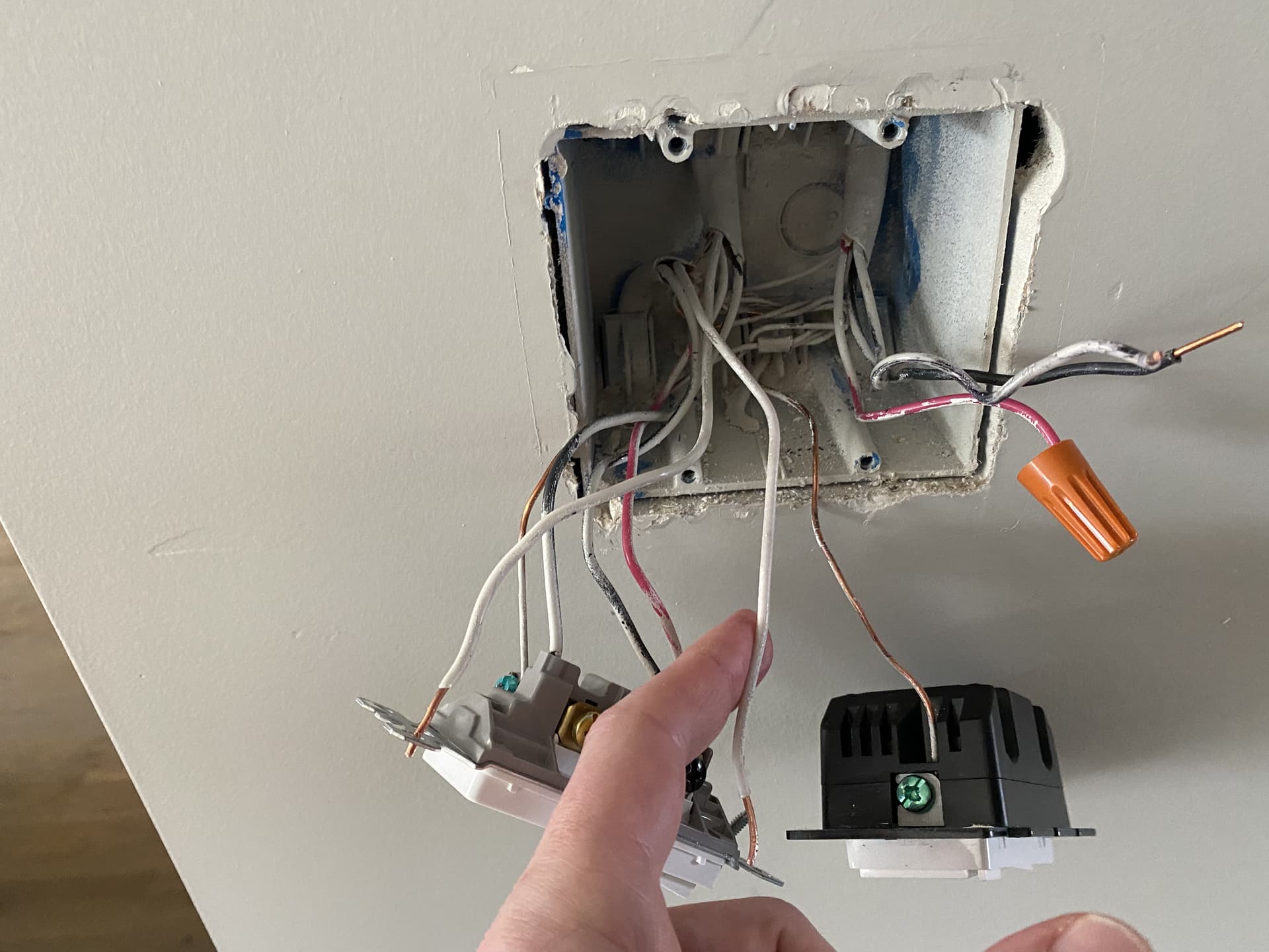
Below is a photo of the SWITCH 1 box. There’s a neutral wire coming from the romex at the bottom left (from the fuse box?)… but no neutral from the romex at the top right, which I believe is connected to the switches I’d like to control.
Did the 3rd switch control the load? Using all Inovelli this way the only switch that will control the load when you install everything is the switch that the load is connected to, which would be the 3rd one. The other 2 will turn on and off, but do not physically control any load (because no load is connected to them). The other 2 have to be properly associated to the 3rd switch to control the 3rd switch.
Yes, there’s power and neutral at the bottom left.
Top right only has those 3 wires coming out of it (red, black and that black and white one). If you look back at the top photo from several hours ago, that black and white one was plugged into load and the switch was turning the lights on and off.
I learned a lesson not taking photos of the original set up. Never again… I have a wire tracer arriving tomorrow which I’m hoping will help. Thanks again for taking the time.
The second box just has 2 of the 3 conductor romex that were used for these lights?
The 3rd box just had a single 2-conductor and a single 3-conductor romex used for these lights?
If the above is true then I think in the 1st box you use the black and white from the bottom left and connect it to the line and neutral of the Inovelli and the black and white from the 3-conductor top right.
In the 2nd box you connect the blacks and whites to the Inovelli line and neutral.
In the 3rd box you connect the black and white from the 3-conductor to the Inovelli line and neutral. You connect the black and white from the 2-conductor to the Inovelli load and neutral.
Box 1 I believe you just want to use the 3-wire, the black/white one is a black insulation coated white so you might want to wrap some white tape around it to ensure it is identified as white. Switch hooks to white and black from it, no load. The whites from the other wires just get joined together.
Box 2 I believe has the power. So, black and white from that gets connected to the black and white from the two 3-wire. Switch gets connected to those as well, no load.
Box 3 I believe has the load. Black and white from the 3-wire goes to line and neutral of the switch. Black and white from the 2-wire goes to load and neutral.
It is possible to wire it so one of the other switches can directly control the load. This could be done to ensure it has control no matter what else might happen to the other switches or z-wave network. The one controlling the load can be slightly more responsive using associations as well. If you want this, the red wire gets used.
Alright, they’re all tied up as you suggested. Switch 2 and 3 have power and 3 is controlling the lights.
Switch 1 doesn’t appear to have power. Any thoughts? It’s probably the least important of the three, but I figure something must be off in terms of how I wired it.
I plugged all the traveler wires in (1 in Switch 1, 2 in Switch 2, 1 in Switch 3)… not sure if that would have any impact.
I’ve learned a lot from this, you’ve been an incredible help.
Double check the black and white connections in switch #2 box. If power is on at switch #2 and the black and white wires that run over to switch #1 are connected to that power then power should be reaching switch #1.