Hi all! Got what is hopefully a quick one for you all. I just wired in a Blue Series 2-1 to replace a dumb switch that controls the outlet a lamp is plugged into in my son’s room (single pole, no neutral - old as hell house). If i leave the lamp with the old “dumb” bulb in, i get electric leakage and the bulb never turns off, so i figure i’m in need of a new bulb. He wants to be able to change colors, so i grabbed a spare Hue bulb and popped it in. That’s where the issues have started.
When i screw in the hue bulb, and i put the switch into “dimmer / smart bulb mode”, and then bind the switch to the light for “on/off and lvlctrl” in Z2M, it seems like the light is suddenly controlling power to the switch. If i press off to run off the light, the switch stops physically responding, and i notice in Z2M that it’s gone dark - Z2M can’t talk to it. If i then use Z2M/HA to turn the bulb back on, then i can talk to the switch again.
The other “odd” symptom i’m seeing is that when it’s on is that when the switch and hue bulb are powered on, the LED strip on the switch is red at the bottom, blue for the rest, and it “flickers” slightly. I don’t see this behavior when it’s in 2-pole / on/off mode.
Anyone have any idea what could be going on here? I’m using the exact same procedure in a different room with the same model switch and some sengled overhead (also zigbee) lights and it seems to work just fine.
Any help you all could provide would be greatly appreciated! Thanks!
Your best course of action here is to re-wire the outlet to be always hot (like a regular outlet). From there you can put your hue bulb in and bind the switch and the bulb.
So if i’ve got the blue switch in “smart bulb” mode isn’t it effectively always on anyway? Like, if i turn the switch off and the bulb turns off, i can still turn the bulb back on so i’m assuming that outlet is still hot (and that power to the outlet is just being passed through) - it looks like more of a control issue than a electrical one, if i’m understanding the situation correctly…
In the US, and probably Canada, the electrical code prohibits using an Inovelli, and most other smart switches, from directly controlling an outlet. This is because the smart switch is not rated to handle anything that can be potentially plugged into that receptacle. I understand that you are just controlling a lamp at the present, but other things can be plugged into that receptacle . . . a vacuum cleaner, for example. If that happens, you probably won’t appreciate the very loud pop and the smoke . . .
You issue is probably stemming from a lack of power to the switch. The good news is there is a proper way to wire this so that the switch will function properly and you will no longer have a safety hazard.
It sounds as if you just have a 2-wire at the switch connected to the receptacle. This is known as a switch loop, where you don’t have a neutral in the switch box. Hot comes in one conductor and goes back to the receptacle switched over the other. The idea here is to remove the switch’s WIRED control of the receptacle, at the same time provided power to the switch with a hot AND a neutral.
Start at the receptacle box. If this is a split receptacle (only half is controlled by the switch), replace it. This box has a constant hot and neutral. Connect thenm to the receptacle and to the 2-wire going back to the switch. (If the receptacle is split, you can also connect a hot to both outlets instead of replacing the receptacle.) Now you have a constantly hot receptacle and a hot and neutral at the switch box.
At the switch box, connect the hot and neutral to the Inovelli’s hot and neutral terminals. It no longer controls a wired load, but it will power up just fine and can be bound or send scene commands.
Hi Bry, thanks for the thorough reply! The issue i have here (and i apologize for not having pictures handy) is that there’s no neutral coming to the box where the switch is, and (as near as i can tell) no neutral to the outlet either. Which doesn’t surprise me, since the house was built in '52. All i have coming to the box are teh load wire coming from (parts unknown) into the box, and then the line wire that lead to the outlet. The load line itself was actually looped over the old dumb switch and then run out back into the wall to the next room over, as a large portion of my (terribly wired) upper floor is wired in series. But as near as i can tell there’s no neutral to work with.
How would i best wire it up in this scenario?
Just for clarity i’ll reply back shortly with pictures. There’s a couple spots in my house that are like this, and ideally i’d love to get smart switches in all of them, so this will be a good “pilot case”.
Pictures will help. You’re probably correct that there is no neutral at the switch box, because that’s how a switch loop works. But there must be a neutral in the receptacle box. If there was no neutral in the receptacle box, nothing you plug into it would work!
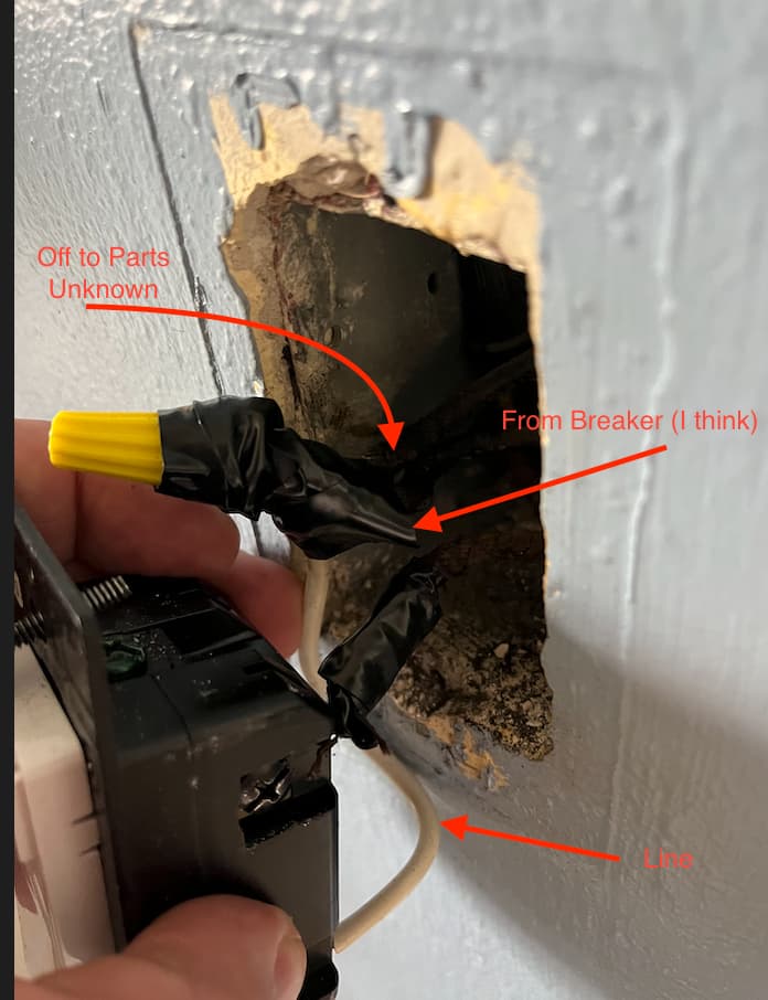
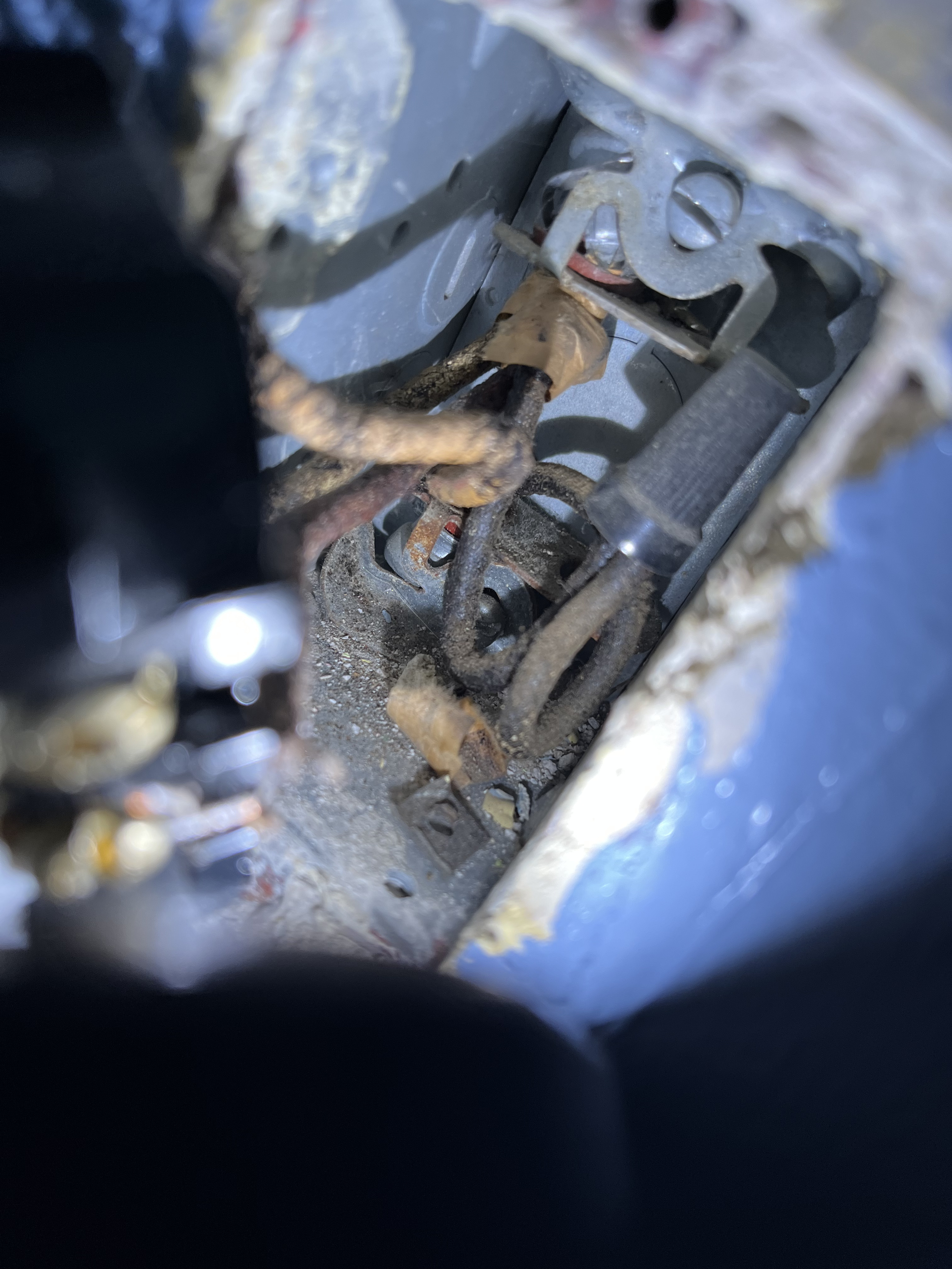
Okay as promised, back with pictures! Apologies for the absolute potato quality, the flash on my phone wasn’t cooperating. I annotated as best as i can. Thanks again for all your help!
Ignore the copious amount of electrictal tape - i’m just hedging my bets given that the old fabric covering the even older wiring is actively disintegrating an has already caused problems in a different outlet (fabric disintigrated, wire touched the metal electrical box, bad things)
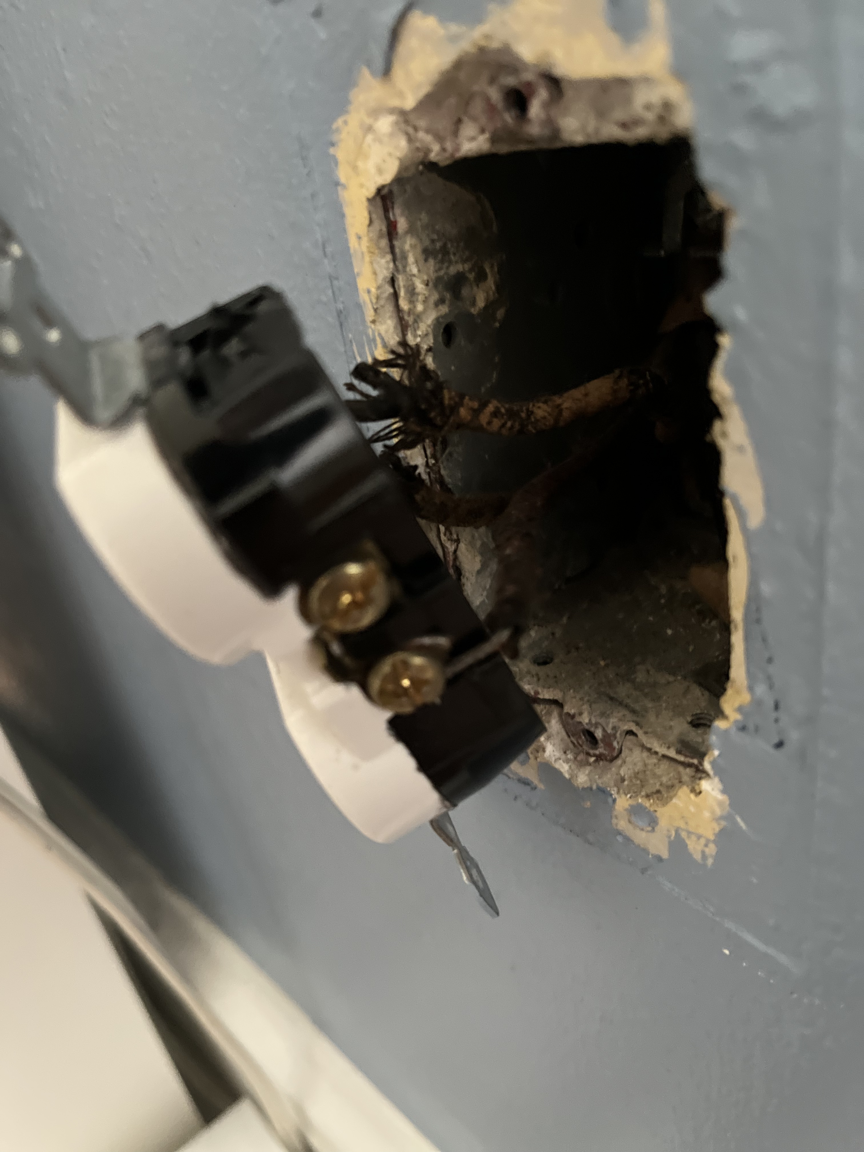
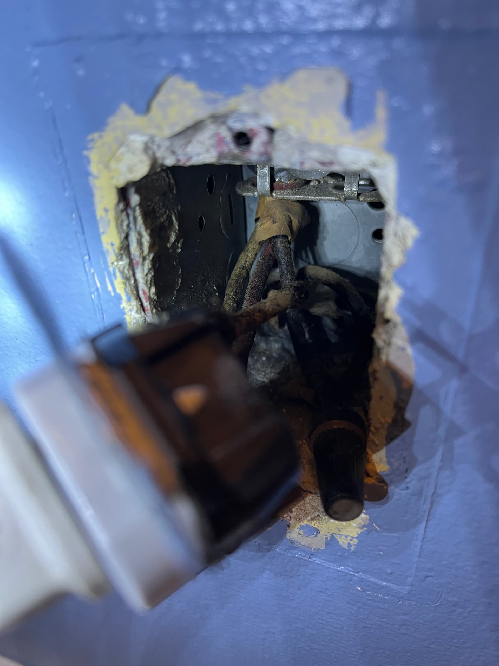
Outlet:
I’d love to tell you which of these wires is which but i honestly don’t know.
I’m around the rest of the day if i can do any tests for clarification, provide better pictures of specific things, etc.
Like i was saying before, i love these switches and are already am happily using them elsewhere in the house (where it’s renovated and i have neutrals and the wiring isn’t a disaster) and this is the last thing in between me and just getting them deployed everywhere!
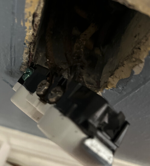
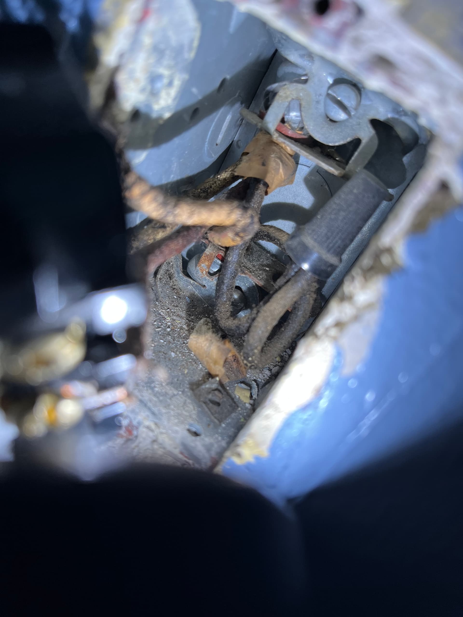
Looking at the 2nd photo of the switch (the better lit one) am i correct in thinking that that capped wire stuffed in the back could be a neutral coming up from the outlet? is there an easy way to tell?
You should get yourself a multimeter. They’re cheap and will really help. Typical wiring is black = hot, white = neutral. If white is hot, it should have a piece of tape or something wrapped around it to identify it. Problem is, you get 1 lazy electrician in there and all bets are off. That’s why a multimeter should be a minimum tool used when doing this stuff. It’s real easy to test the wire and see which one is hot.
I’ll let @Bry handle the specifics here since these pics are hard to make out what’s what and he’s probably the best guy on this board to nail down old wiring.
But here’s a very simplified version of what’s got to be done. If the switch used to control the plug, you’d have at least 2 wires going from where your switch is to where your plug is (probably 1 black and 1 white). When a switch is controlling a plug like that, what’s happening is the power is fed through the switch through 1 wire then back to the plug through the other. When the switch is off, no power flows to the plug. When you flick the switch on, it completes the circuit and sends power back to the plug.
So what we’re saying, instead of using both wires going to the switch for power, you’ll use 1 as power and the other as neutral. Your plug will have both coming in. Your plug will also only need power and neutral so this should be pretty simple. What you’re going to end up with is a plug that’s always on like any regular plug, and a switch that’s powered but doesn’t directly control anything. BUT because you can do binding you’ll be able to easily make the switch control the bulb.
So for the receptacle box. I only see two conductors (not counting a bare ground if there is one) coming into or leaving the box. Still tough to see from the pictures so you will have to confirm. Is that correct?
Here’s a couple more shots. To describe it for clarification:
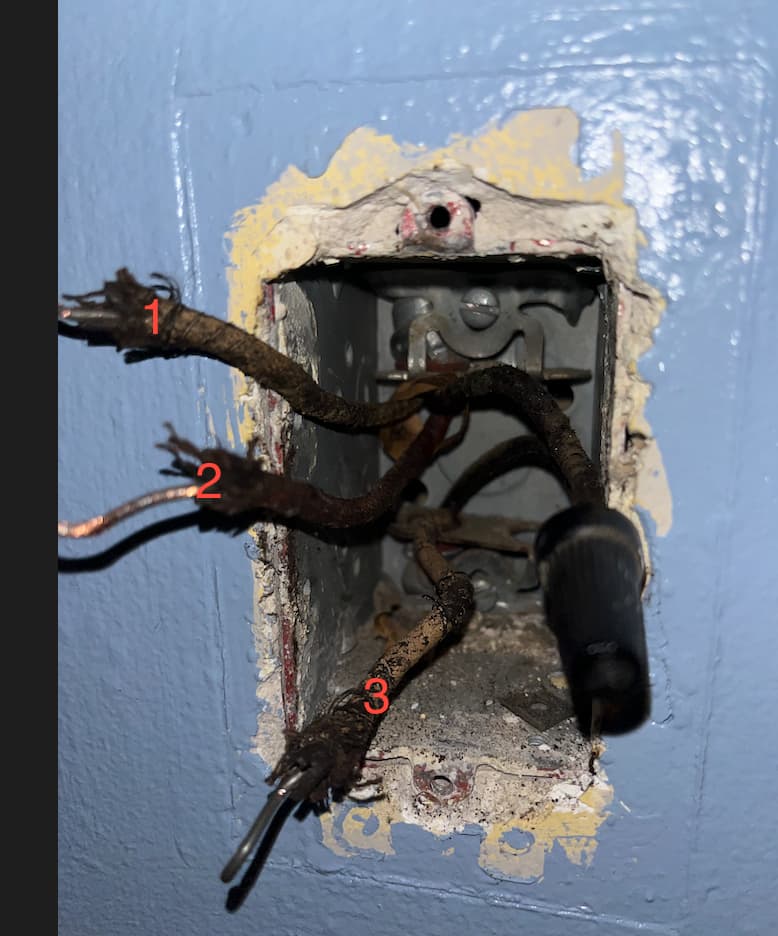
I see a black wire on the right (the one with a wire nut on it) comes up into the box from below, goes into the nut, and then goes right back out the top of the box. Doesn’t interact with the outlet at all.
There’s a white(ish) wire that comes up from below, goes into the upper silver terminal on the left side of the outlet.
Theres another white(ish) wire that comes out of the lower silver terminal on the left side of the outlet and goes out the top of the box.
Lastly, there is a red (hard to tell because it’s so dirty) wire coming out of the top of the box and into the lower terminal on the right of the outlet.
The bridge tab on the outlet is still in so it’s not split.
My entire house in a nutshell. When we opened up the basement to do the renovation they were going to try and re-use the electrical down there and like two hours in the contractor came back and said “we’re ripping out all of the basement wiring because none of it makes sense”.
Sorry, I can’t make much of your description. And your pictures have to have everything pulled out. If you can’t see into the box and see exactly how many conductors are coming into it, the pictures are not going to be of any value. Your pictures have that black bundle tucked up into the box. I can’t figure out if it’s hiding anything or not so I have nothing I can offer you at this point.
So let’s try this. That cloth covered wire is similar to Romex in that the conductors are bundled together. There is a 2-wire possibly with the bare ground. And a 3-wire, possibly with a bare ground.
So what do you have coming into the receptacle box. I see a red conductor now which makes me think you have at least a three-wire. In addition to that three wire is there another two wire coming into the box as well?
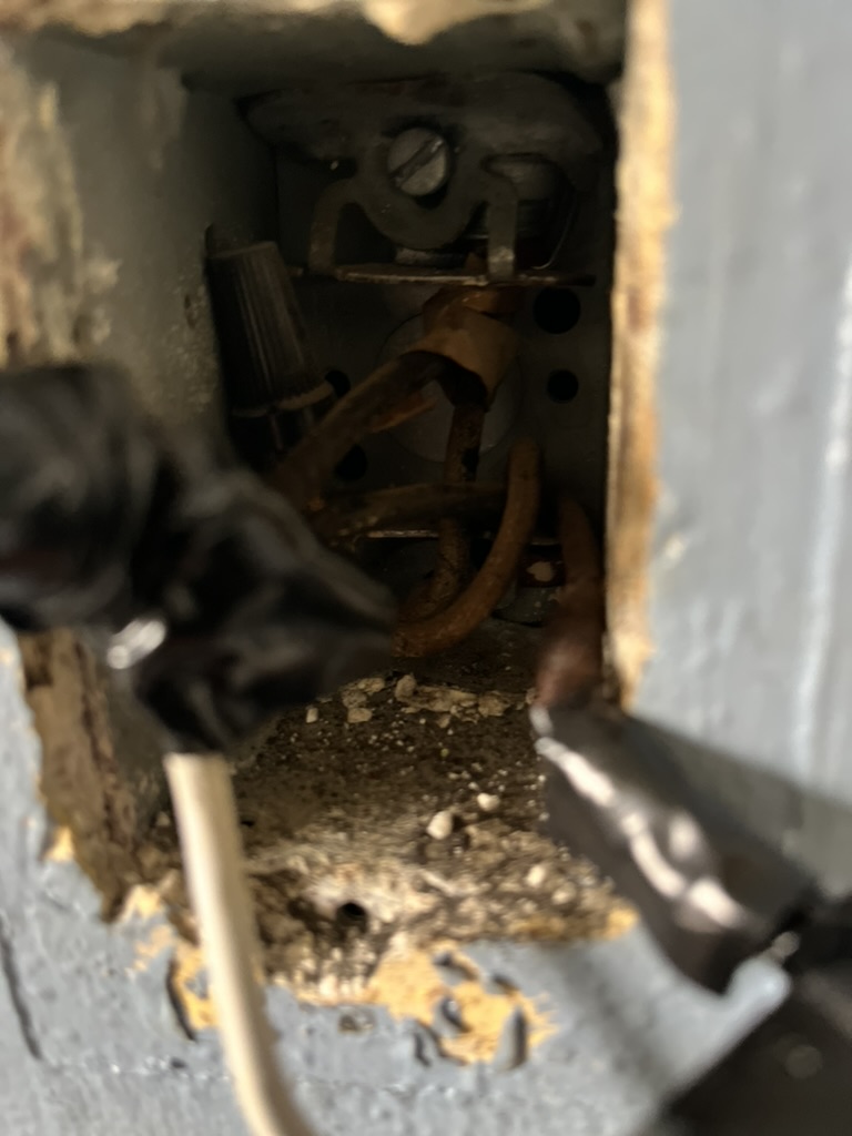
That’s about as pulled out as i can get it - there’s not a lot to work with.
There’s nothing hidden behind the wire nut on the right in the photo - just empty space back there. two wires come up from the bottom, three go out the top.
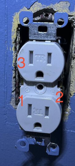
For the record, here’s where the numbered wires plugged into the outlet, in case that’s helpful:
Which side of the receptacle has the brass (gold) screws? The “2” side or the “1/3” side? I’m guessing the brass is on the “2” side but please confirm. Looks like it from your prior pics.
Just making sure I’m not seeing a shadow. On the right side of the box is the wire nut. It is joining a conductor from the 2-wire at the bottom and a conductor from the 3-wire from the top? Is that correct?
You’re correct on both counts - brass on the 2-side, Silver on the 1/3 side, and yes, the wire on the right comes out the 2-wire at the bottom, and connects at the Nut and runs off into the 3-wire at the top.