I fully understand now. I’ll go straight to the point:
I was under the impression that there were two buttons for the extra config buttons
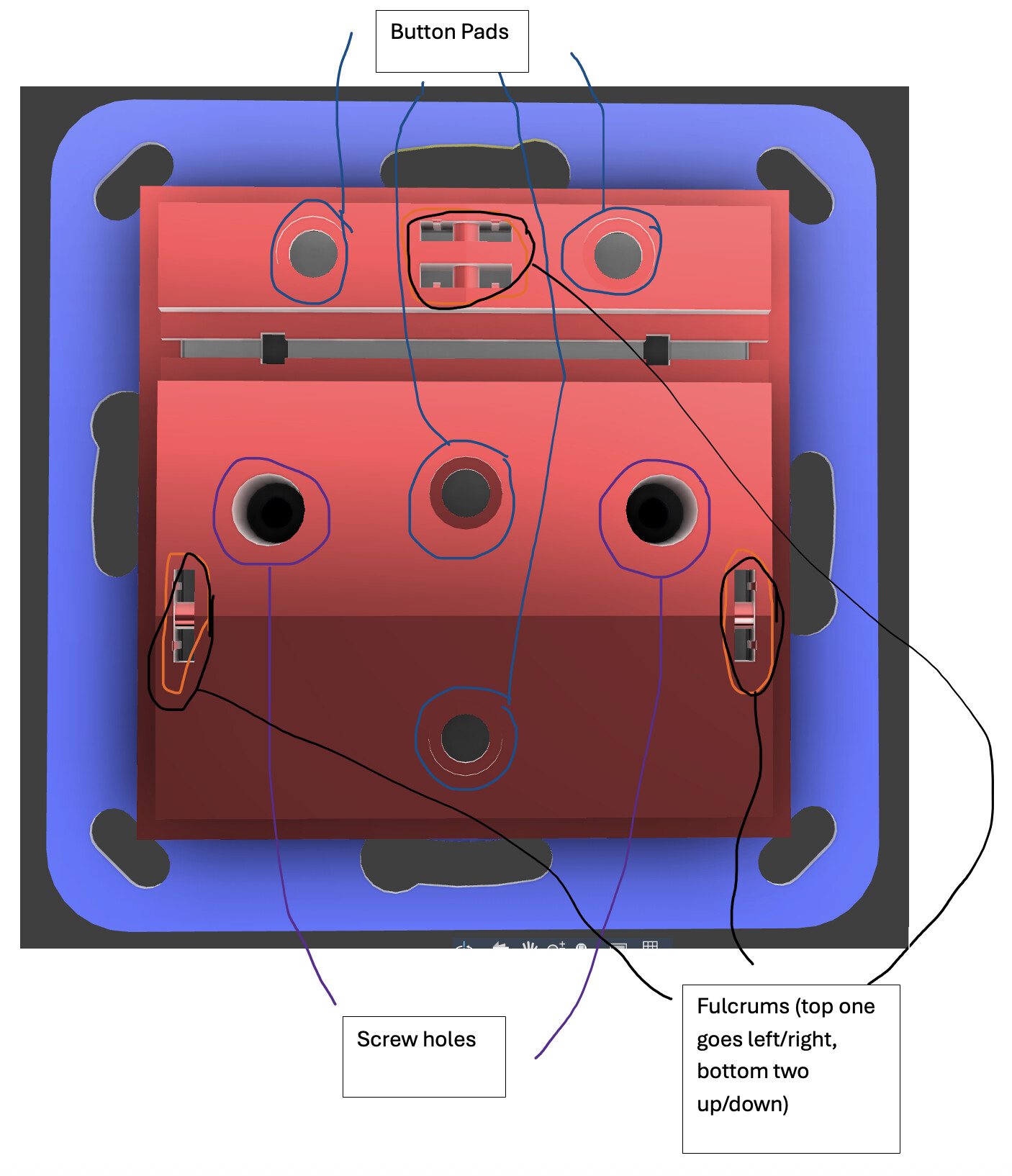
Looking at the design, I would say it’s NOT an issue that the button(s) are on a fulcrum, and you press either A or B once at a time. The little ridge in the middle gives you enough of a clue that there are two buttons and not one.
The amount of button possibilities are so many with single press, double press and long press on the up, down, A and B buttons that an “AB” button press isn’t needed.
I don’t think any sort of light leak will be an issue. Looking at your mock-up in the futuristic home is exactly how I’d imagine it’d look and there’s negligable light leak there, if any.
I think I’d also expected the two config/scene buttons to be individual and not combined on a fulcrum, but it does still work visually with the groove to indicate that it’s two buttons. I can’t imagine wanting or needing to press both together as opposed to in quick succession, and it’d be an obvious limitation when you’re creating scenes.
I like the Knight Rider mock ups, haha. If there’s a worry about light bleed vs. functionality, there’s maybe a software solution? Use the full width of the LED bar for indicating percentage while dimming, but exclude the end LEDs for status and notifications to get the Knight Rider effect.
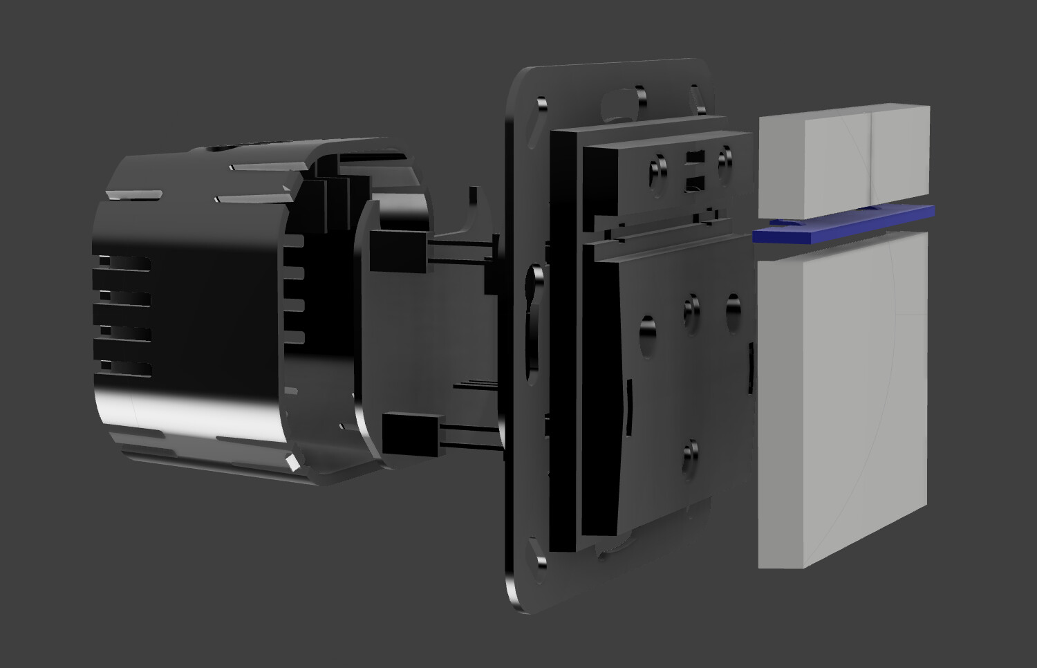
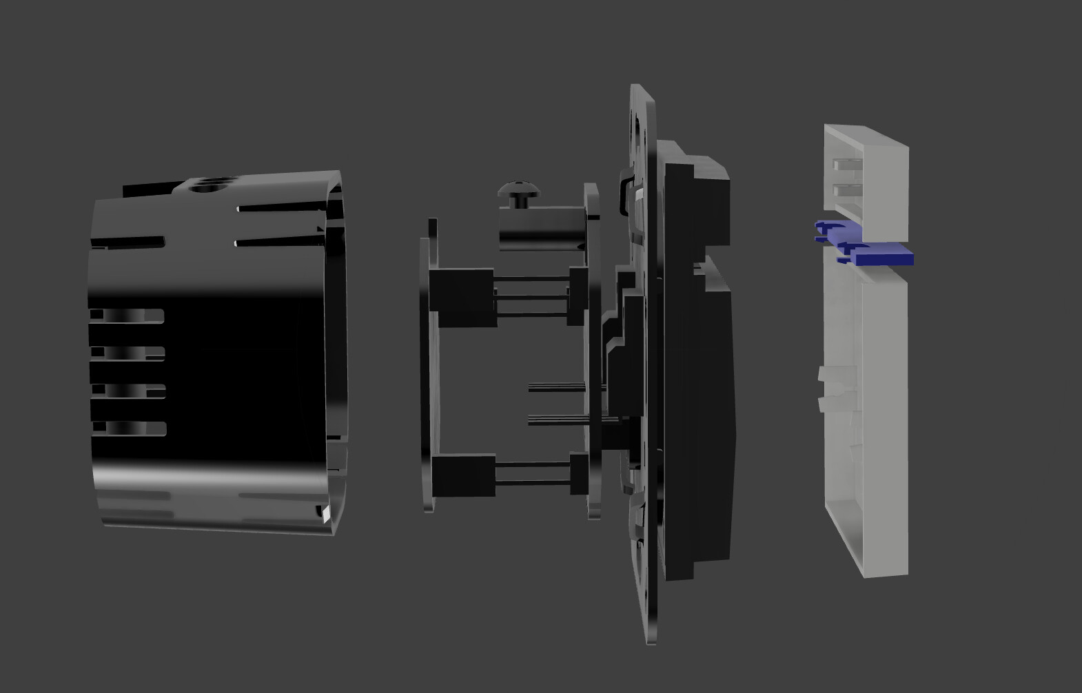
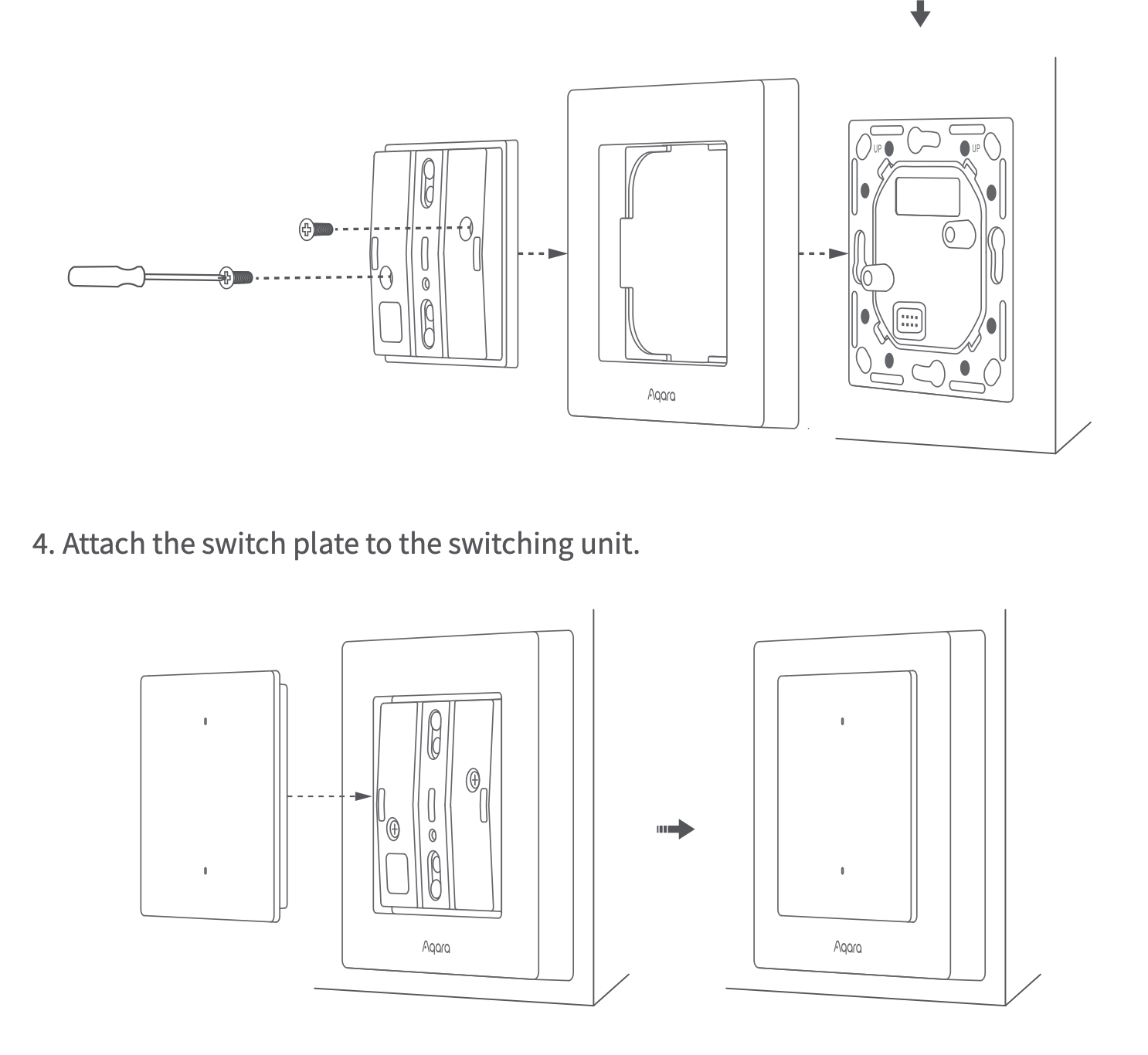
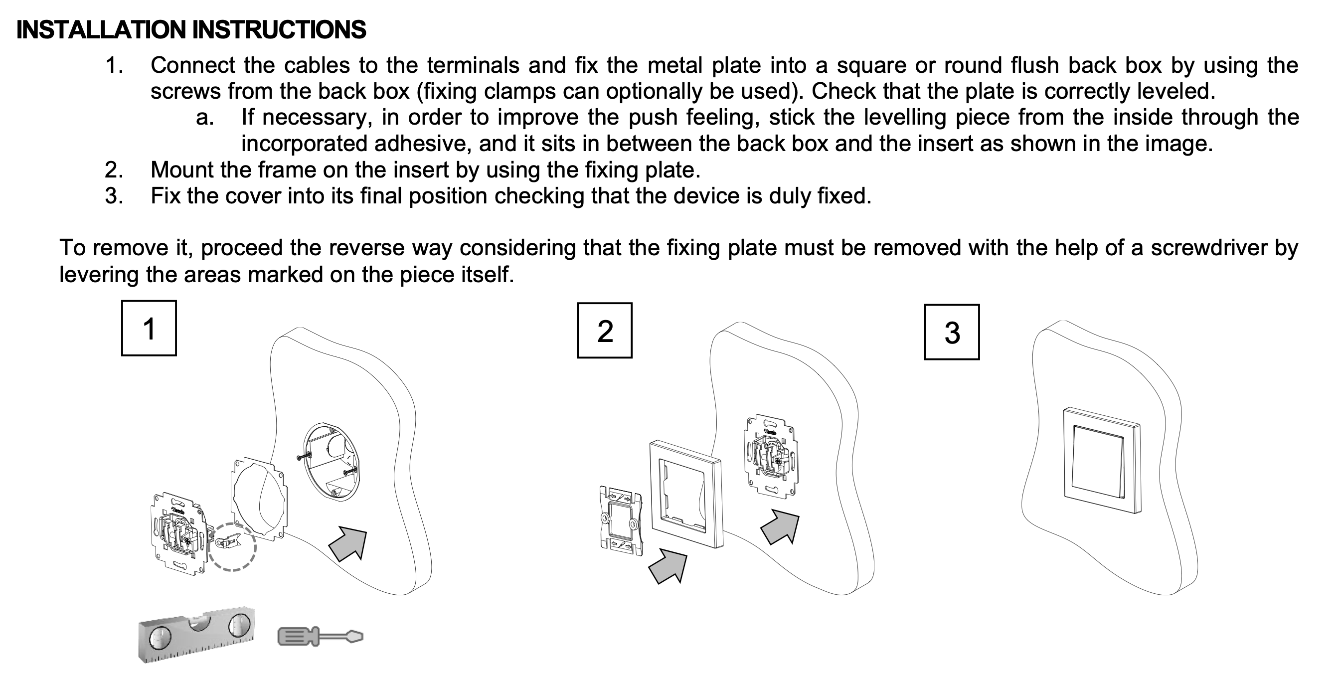
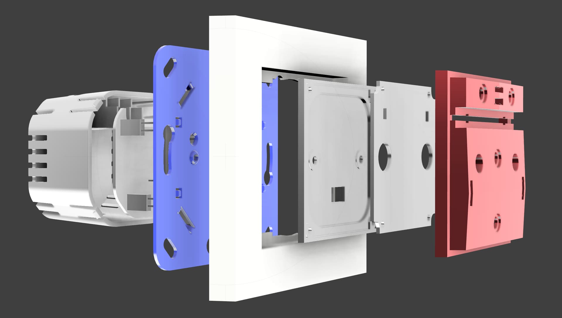
I’m about the general assembly of this. I think it’s implied from some of your images, but is it a four part construction that goes electrical base > outer frame > switching unit > switch paddles?
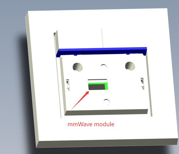
mmWave Module Development Update (For a Future Product)
NOTE (EH): THIS IS JUST THE DESIGN FOR A FUTURE PRODUCT (MMWAVE) - WE ASKED THE ENGINEER TO DESIGN THE CURRENT PRODUCT (NON-MMWAVE) TO BE COMPATIBLE WITH A FUTURE MMWAVE PRODUCT (SO, WE WOULDN’T HAVE TO PAY FOR ADDITIONAL TOOLING).
THE NOTES BELOW ARE IN REFERENCE TO HOW THEY HAVE SUCCESSFULLY COMPLETED THE DESIGN TO INCLUDE AN MMWAVE MODULE FOR FUTURE PRODUCTION.
mmWave module development is complete.
The mmWave module antenna is smaller than the US switch, with only a small visible window.
Detection performance of the new mmWave module is identical to that of the US switch.
The cost of the new mmWave module is similar to the mmWave module of the US switch.
Community feedback indicates support for keeping the design with the fulcrum.
Community feedback indicates no concern regarding light leak, pending sample review.
Highlights
The mmWave module development is complete and its detection performance should be identical to the US switch, but further testing is required in the future.
The antenna design is compact, featuring a smaller size than the US switch with only a small visible window.
Potential cost differences between the new mmWave module and the US Dimmer vs US mmWave are an open question.
Light leak analysis is pending review of physical samples.
Decisions
Proceed with the 3D samples as is (non-mmWave), based on community feedback regarding the fulcrum design and light leak.
Action Items
Discuss the current mmWave module design with the manufacturer for potential improvements, but continue as-is for the non-mmWave version.
Disclaimer: This update was generated automatically using AI to summarize recent internal project discussions. Personal names have been omitted. It may omit details or misinterpret context; please reply if clarification is needed.
Yeah, I think this will have to be something we analyze when we see it, but I think the solution would be to tune down the brightness of the LED if it bothers someone. And yes, at the same time, we can just have the first (far left) and last (far right) LED’s either disabled or set a specific dim intensity on those to “taper” off the bleed if it’s a concern.
Can you explain further? Sorry, I’m not following – maybe I just had too much turkey from Thanksgiving yesterday haha.
If you’re talking about how the switch is assembled, then it would go something like this:
Outer shell (back) - plastic > Inner PCB(s) (likely two) sit inside the outer shell > Metal Plate screws into the plastic shell and locks everything into place > Paddles + LED Bar snap into the metal plate (three pieces – upper paddle on the fulcrum, LED Bar, and lower main paddle)
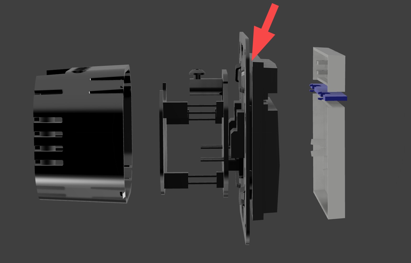
OK, I think there’s a detail being missed here, for how it is that the frame is secured in place.
I think this might actually be in your design, since there is a gap between screw plate and what I’m going to call the button module. But that needs to be removable or shrunk down further with a retaining bracket so that the System 55 frame can have its internal lip go behind and be fixed in place.
The Red part is the recolored piece behind the paddles (what the paddles and LED Bar snaps into). The blue part is the metal piece.
They didn’t draw any screws in the AutoCad file, so I can’t confirm, but I will ask the engineer for clarity. I think this was the preliminary drawing and maybe they just forgot to add screws
But, it appears they are handling it similar to how Aqara does it.
But, just so I’m understanding, the part that’s important is the blue part (as shown in our diagram), correct? We need to ensure we have those slots lined up so the faceplate can go over it and then the red part on top of the faceplate to, “lock it in”?
What I think the difference is, is that the video shows a hollow middle section on the metal part (and I think Aqara does too) whereas ours has a solid plate with a small hole in it (which I’m assuming is where the PCB 1 plugs into PCB 2.
I’m happy to pass along some clarifying questions to the engineer (who uses the same style switches in his home) if you’d like?
Yes matte was the word I was missing. Sorry I’m not a native English speaker. But I am really excited for these as I just tested the Aqara H2 and found out that they are actually horrible. So now I found this and these look really good. I think they are worth the wait.
Hey all, I’ve been quietly lurking for some time now and glad to see a product like this making positive steps forward. I’ve been holding off fully fitting my house with smart switches ever since seeing Inovelli were working on an EU project.
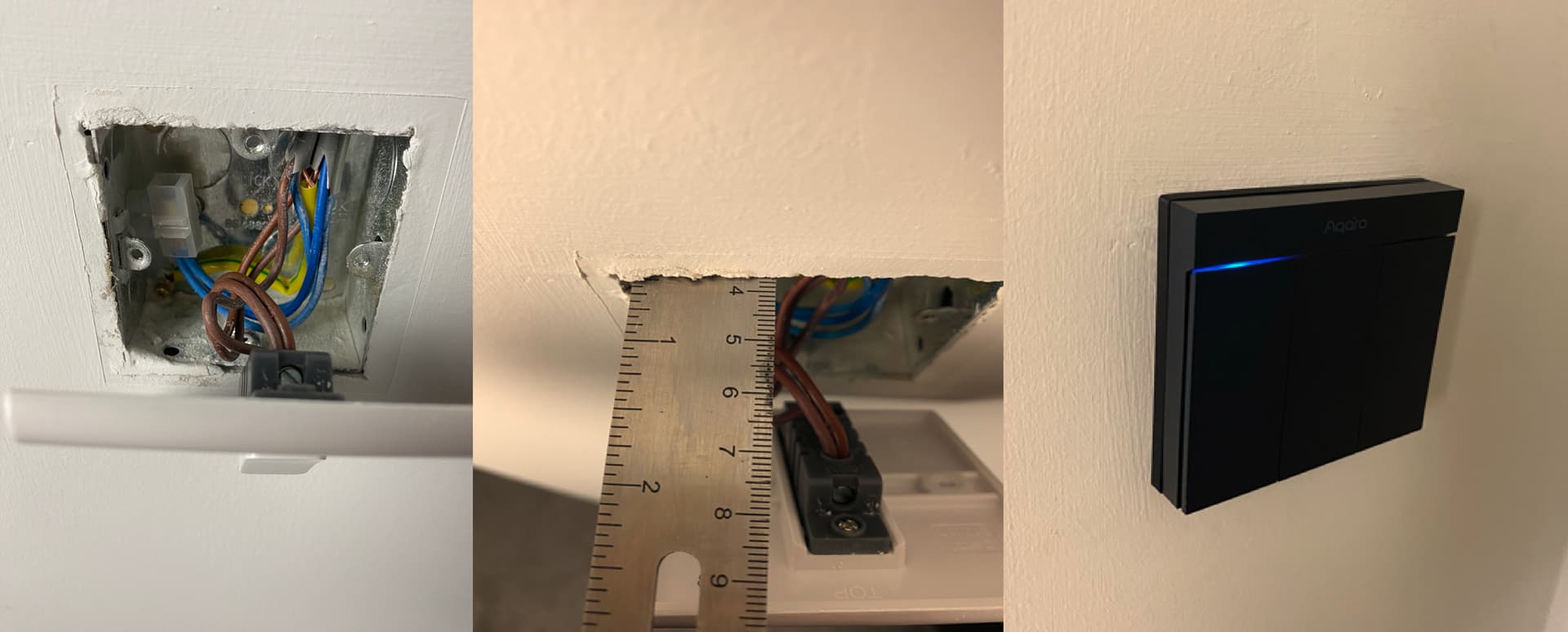
Just following the discussion of the size of our back boxes in the UK, here was my personal situation on a timber frame new build which is a popular house type in the UK, especially Scotland and other Northern EU countries.
I couldn’t fit the Aqara H1M due to how many wires I had in the box even though it’s 36mm deep, I had to 3D print a spacer just to make it flush against the wall as seen in the photos.
If the depth of the switch has to be what it is, may I suggest that optional spacers could be purchased to allow people with fitment issues to have a flush finish? At least this way they would all be the same material/colour. (apologies if this was already suggested)
I also like the idea of dark grey/black matt finishes but realise that initially you may have to limit to white just to get an idea of the demand.
Exploration into offering a matte finish option for switches (both EU and American versions) is underway.
A proposal was made to implement multi-language support for Mode Select on European switches, with potential to unify US and EU firmware.
Risks/Blockers
Tooling for glossy and matte finishes can only support one process per tooling, or requires two cavities with potential for higher unit cost if order ratios are uneven.
Cost for finishes is variable based on total quantity.
Uncertainty regarding the full capability of the “Localization Configuration Cluster” to support multi-language conversions.
Timeline
No specific timeline updates this week.
Decisions
The Minimum Order Quantity (MOQ) for finishes has been set at 3,000 units.
Action Items
Review the newly provided STEP file.
Determine the desired order ratio for glossy versus matte finishes.
Research the “Localization Configuration Cluster” to assess its functionality for enabling multi-language conversions.
Investigate the feasibility and cost implications of implementing multi-language firmware via Mode Select for European and US devices.
In my experience spacers are usually sold by the same company that makes the frame. I have schneider exxact switches an when I needed a spacer to fit a Plejd dimmer behind it, the only one that sits flush with the wall and frame was the one from the same maker.
All designs, including structural, PCB hardware, and mmWave module designs, are complete (NOTE: As a reminder, this switch will not have mmWave, the team has just designed the switch to account for this in future iterations).
Risks/Blockers
None identified.
Timeline
Samples are expected to be completed in three weeks.
Decisions
None explicitly stated.
Action Items
Proceed with manufacturing samples for initial testing.