I understand the very basics of electricity. I understand sharing a neutral between circuits is not proper wiring.
With that said, here are a couple questions.
1.) it appears, sadly, throughout my home, any dedicated switch in a 3/4 way setup, there are no neutrals in the switchbox. If a switch is wired to a single light or an outlet, the neutral IS in the switchbox. When turning off the breaker at the panel, in some cases, all switches in the same switchbox lose power. Is it safe to “assume” if a neutral is in the switchbox for a 1-way setup next to a switch that is part of a 3/4 way setup, I can “steal” that neutral for all switches since it is the same circuit? Or is it that multiple circuits can be wired to the same breaker and therefore this wouldn’t be a safe/approved way to wire a switch? I do know, in some cases, there is piggybacking done in the panel at the breaker if that matters, which I also know isn’t proper.
2.) if the above wiring is safe, would I be able to use a single inovelli dimmer/switch at the switchbox location where a neutral exists for reasons mentioned above and not need smart add-ons one the other locations where the possibility of neutrals may not exist? I know I have to make sure the line to the switch box needs to be located in said switchbox.
To answer your question in #1 first, as you suspect, no it wouldn’t be safe since you have piggybacked circuits, which are a danger in themselves. Do you have room in your panel for additional breakers? I would make adding breakers your first priority.
But getting back to the reason that you are asking . . . I’m not saying that the 3/4 ways aren’t wired as you describe, but it would be highly unusual. If you think about how you would wire that as an electrician, you would be starting with a hot/neutral in a box that you are using for something else. Despite the fact that one of the switches you are about to wire in a 3-way is in the same box, you send the hot and neutral to either another box, and then to a light (or vice versa) and then back. That just doesn’t make any sense. Most electricians wouldn’t wire it that way, but nothing would surprise me. And of course, you can’t discount homeowners and contractors doing strange things.
Lights that start with a hot to the box resulting in a non-neutral usually occurs at the end of a run. That’s not what you have, as you’ve described it.
I’m not saying you are wrong, but I would suggest that you get a second look at your 3/4-ways to confirm your suspicions. I know from experience that these legs can be confusing and that things aren’t always what they first seem to be.
In any event, before you start swapping out switches, photo/video document the connections. When you do this, insure that you can see all the connections and into the boxes, including into the boxes so that you can see the conductors coming into the boxes.
I think to answer your question more succinctly YES. If you have two sets of switches in a box and both are obtaining power from the same circuit then it is safe / legal to use that return for all the switch wiring whether it be Smart switches of an illuminated switch etc.
Thank you for your response. I will take a 2nd and 3rd look to confirm things.
I’m getting to this conclusion based on metering I’ve done and also just visuals when opening different switch boxes around the house. For example, I have one dual gang switch box that houses a switch that controls a duplex outlet in the room and switch(1-way) that controls two recessed lights in the ceiling. Another switch box houses three switches. One switch(2-way) controls a light fixture over the kitchen table.(one more switch on the other side of the room) One switch(3-way) controls another light in the hallway adjacent to the kitchen.(two more switches, one at the other end of the hall and one at the top of the stairs) The last switch(3-way) controls 4 recessed lights in the kitchen.(two more switches in the kitchen on opposite walls). A third switch box has 4 switches. One switch controls 2 exterior sconces on each side of the front door. One switch controls exterior recessed lights over a porch area. One switch controls another set of exterior recessed lights over a side porch area. Finally, the last switch is the 2nd third of the light in the hallway adjacent to the kitchen mentioned above.
Now… with that all said. The first box mentioned above has a bundle of neutrals in the switch box. The second box above has no neutral bundles contained within the switch box and the last switch box above does have a bundle of neutrals.(two of the four switches in this last box are 1-way, one is 2-way and one is a 3-way).
I wrote all this out to make sure I’m understanding everything i have and can implement your response into it. In the case of the last switch box with 4 switches in it, I know that 3 of the 4 switches are on the same circuit. The exterior light switches are on the same circuit and the hallway light is on a separate circuit. I looks like anywhere a multi-way switch setup is used, the electrician wired the house cheaply by putting the neutrals at the lights so they could use 3-conductor wire everywhere in the house. Where it’s a 1-way, they didn’t need the traveller so there’s a neutral bundle. I draw everything out because I don’t do this for a living and I do confuse myself easily. Maybe the more in depth explanation makes more sense as to why things were done the way they were?
Without turning this into a therapy session. After a couple years of living in the home built in 2001, we found out a builder built it, ran out of money, sold it to the 2nd owners and then ran. So we’ve found more half-@ssed things around the house. Thankfully, carpentry is my trade, so i’m able to safely and confidently do those repairs and fixes.
Not sure I follow. 3 and 4-ways are run with 3-wire. That’s how it’s done. That has nothing to do with where the neutral is. Typically, the neutral is sent over one conductor with the other two used as travelers for the switched hot.
Sorry, 3 conductor being 2 + ground so when used in 3/4 way setup, I have a hot and traveller along with grounds. Appears I used the wrong term? X conductor wire being the number of wires NOT including a ground?
NP. Yes, a 3-wire is three insulated conductors plus a ground. A 2-wire is two insulated conductors plus a ground. For descriptive purposes, the ground isn’t counted.
Also be aware that you can run a 3-way leg via 2 2-wires. I’ve seen it occasionally. In that case, you actually have an extra conductor if it’s run properly. Not saying that’s what you have, just throwing it out there as a possibility.
I’m going to confirm everything and take some photos tomorrow. If you don’t mind, I’d like to send up here if you could take a look and confirm what is happening. I’m going to take photos of the 3 different switch boxes I described earlier.
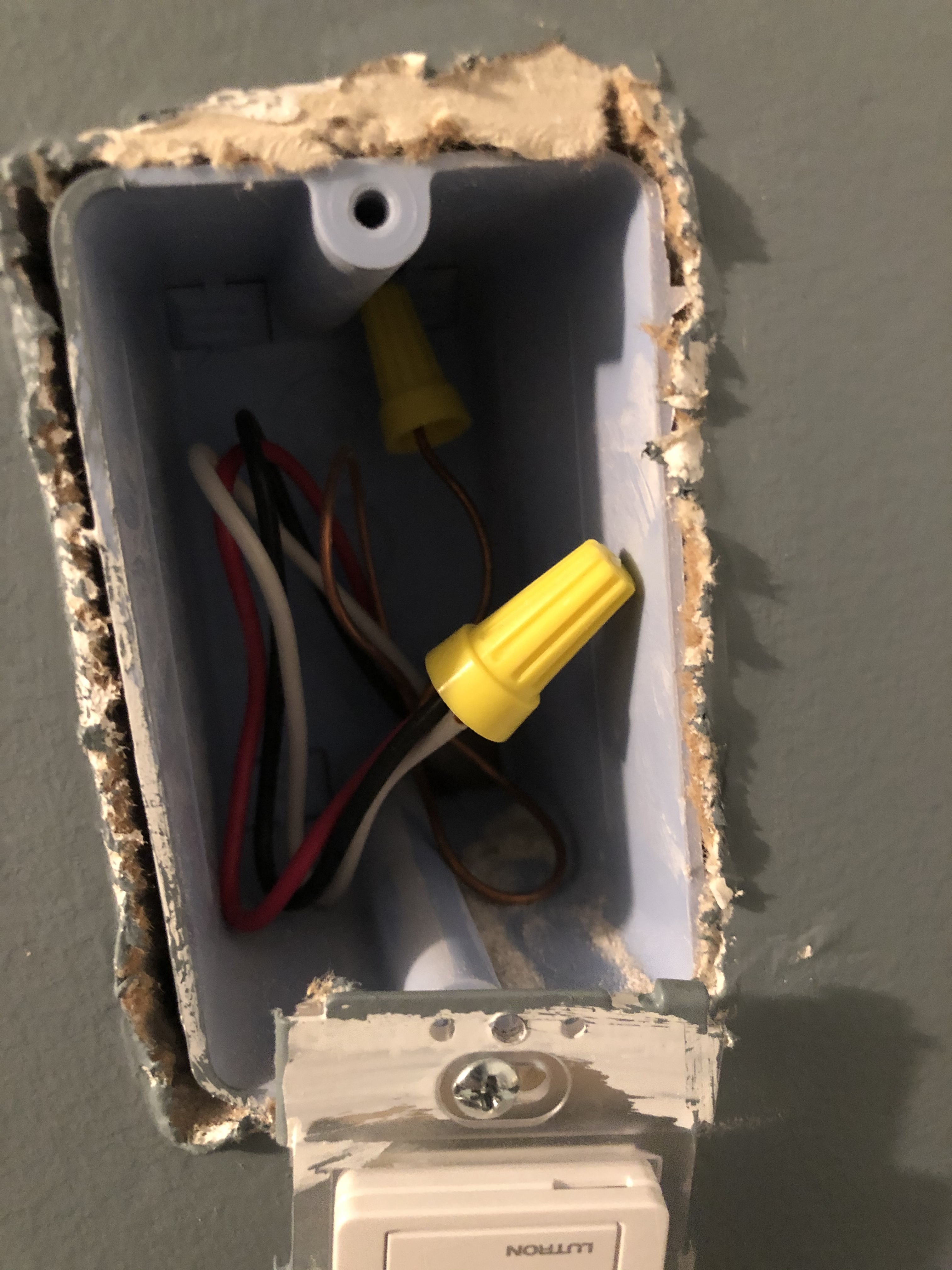
Here is a pair of boxes from a stairwell that I’ve installed Lutron Casetta switches on due to not having a neutral. I have inovelli dimmers and GE add-ons ready to swap out the Lutron switches because the hub location is too far away for a consistent signal.
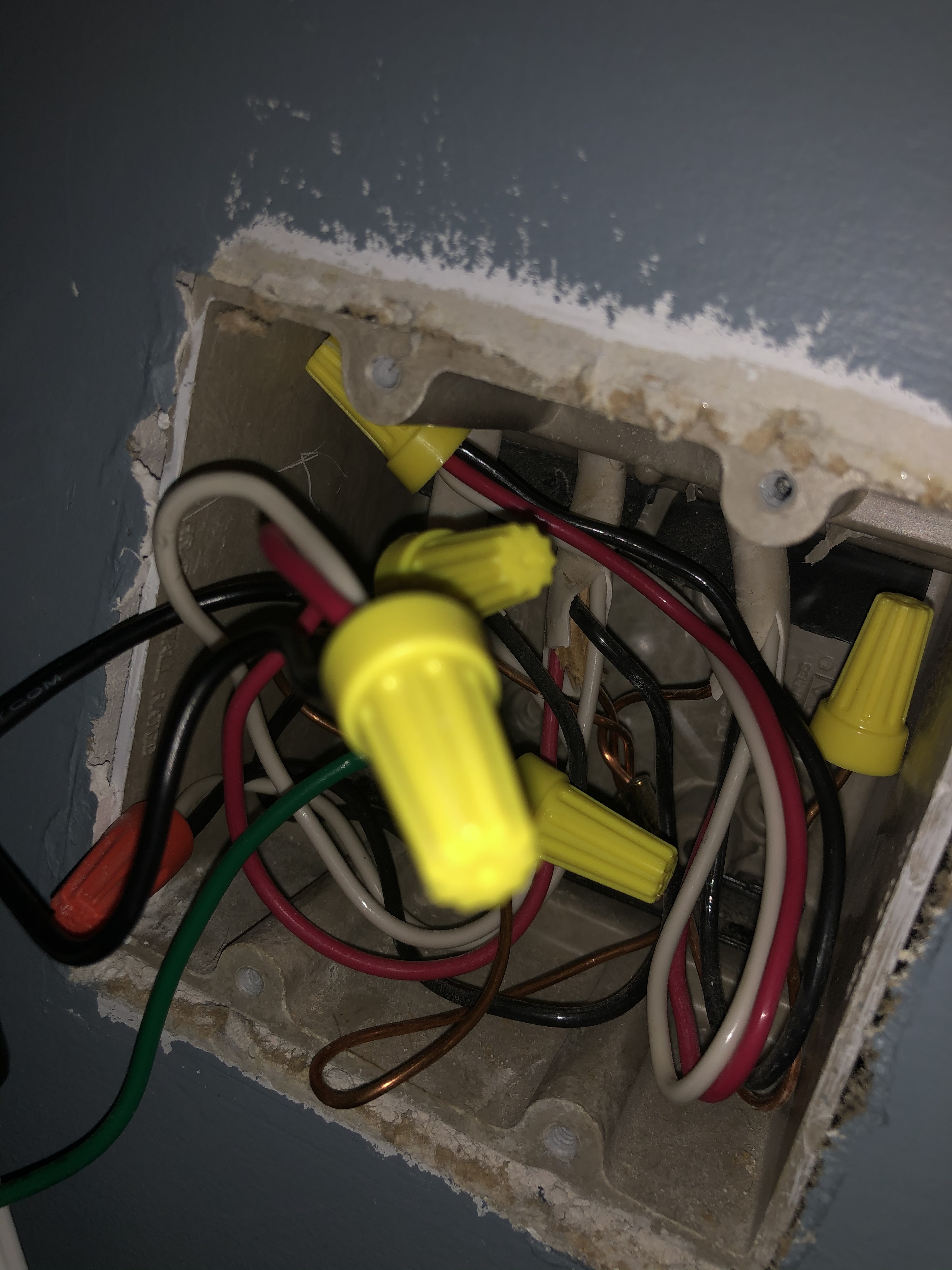
The first picture is of the Lutron Pico Remote location which is why everything is wire nutted together. The second picture is the other half of another remote, so disregard the bundle of 3. The ground capped off is also from the other remote. The remaining wires are for the Casetta switch. Hope these help to start.
Ha! You can’t fish all that out? Sorry, fat fingered the wrong photo from my phone. The photo I took was grounds capped and the bundle wire nutted from another 3-way setup using a pico remote. I pulled all wires out for what I wanted to send you. I put the photos on my computer. I’ll send it over when I get back home.
Sorry for the delay. If you can still assist, that would be greatly appreciated.
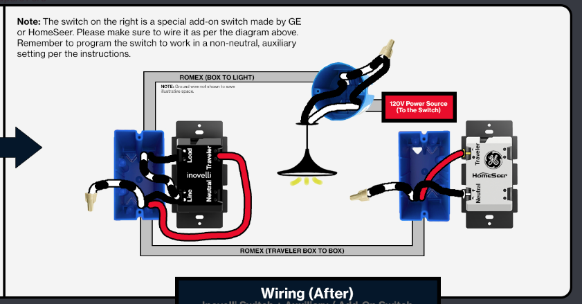
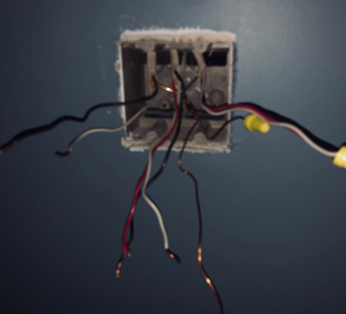
So here’s the correct pic. Three romex all coming in from the top of the gang box. From left to right. 2-wire coming from the light fixture. The black is my load, the white is my line. The white is carrying 120v at all times. Middle 3-wire is the romex to the other switch box. The right romex is my traveler from another switch unrelated to this fixture i’m trying to wire that is currently bundled together for a Pico remote switch. I’m using the wiring diagram attached to wire things up. I have control of the fixture via z-wave, i have control via the inovelli dimmer switch. The one thing I can’t do is turn it on via my GE add-on from the other box. I can turn it off from the GE add-on, just can’t turn it on.
Part of the reason for the delay getting back to you is I wanted to get all the info gathered so could respond with better information. It seems, except for the basement where these photos were taken, that all 2-way and 3-way switches were wired with neutrals in the switch boxes. For some reason all 4-ways in the house are wired power to the light first with no neutrals in the boxes. I had Lutron Casetta and Pico’s originally in the two basement locations but the distance to the hub made them unreliable. I have z-wave all over the house so I can get a good signal with the Inovelli dimmers. I’ve had no issues with 4 other 2-way applications with neutrals and one 3-way application with GE add-on with a neutral. Just these non-neutral applications that are giving me a hard time. I’ve searched around and noticed a number of posts reminding people to make sure the parameters of the switch are set correctly. Via the smartthings app, I have the AC Power type set to Non Neutral, or ZERO when looking via the IDE and my switch type is set to 3-way Momentary or 2 when looking at the IDE. So at this point, I’m not sure where to go. I’ve tried two Inovelli dimmers and also tried two different GE add-ons. THe first Inovelli had trouble pairing with the new ST app, so i paired a new one and was able to get it going except for the “turn on from GE” part of things.
Thanks again for any help and guidance.
Bryan
[EDIT] So the add-on will turn on the light every 10-15 tries. Weird thing is, when tapping the top of the add-on, that will also turn it off. I can’t imagine, I’ve gotten lucky with a couple of bad switches? Does that make any sense?
Ok, thanks for the new pic. I’m going to recap my understanding to make sure we’re on the same page.
So the last picture you posted is one side of a 3-way. The two Romex that relate to the 3-way are the two leftmost. You believe that the 2-wire comes from the light and supplies power. The 3-wire goes to the other box which you posted a picture of earlier. It’s a single gang box that just has one 3-wire Romex in it.
Presuming that is the case, this is a non-neutral 3-way. You don’t have a neutral in either box.
So to confirm this, using a meter, if you test between the white from the 2-wire and the bare ground and you should get 120V. (According to your post, the white from the 2-wire is the Line.)
So if that confirms, the wiring diagram you posted last is correct. Just to confirm the connections, in the 2-gang box with the 2-wire and the 3-wire, the white from the 2-wire goes to the Line terminal and the black from the 2-wire goes to the Load terminal. For the 3-wire, cap off the white at both ends as it’s not used. The red from the 3-wire goes to the Traveler terminal and the black from the 3-wire goes to the other backstab on the Line terminal.
In the single gang box, white is capped off, red to Traveler and black to Neutral.
So it sounds like you wired this and it’s not working properly. Double-check your connections and if need be, post pics with the the switches connected to that we can see the connections. I would start by disconnecting the 3-way and see if the Inovelli works properly on its own as a 2-way. (You’ll have to change the dimmer’s parameters.) Then add the 3-way back in and test.
Double check your parameter settings. They are correct as you described them but you can set them at the switch as well. Try setting them to an incorrect parameter and then put them back to the proper one.
Which Inovelli dimmer are you using? Which model GE aux? Is the Aux one of the supported models?
What is your load? LED? Which ones? Check the supported list if they are LEDs. You might need a bypass.
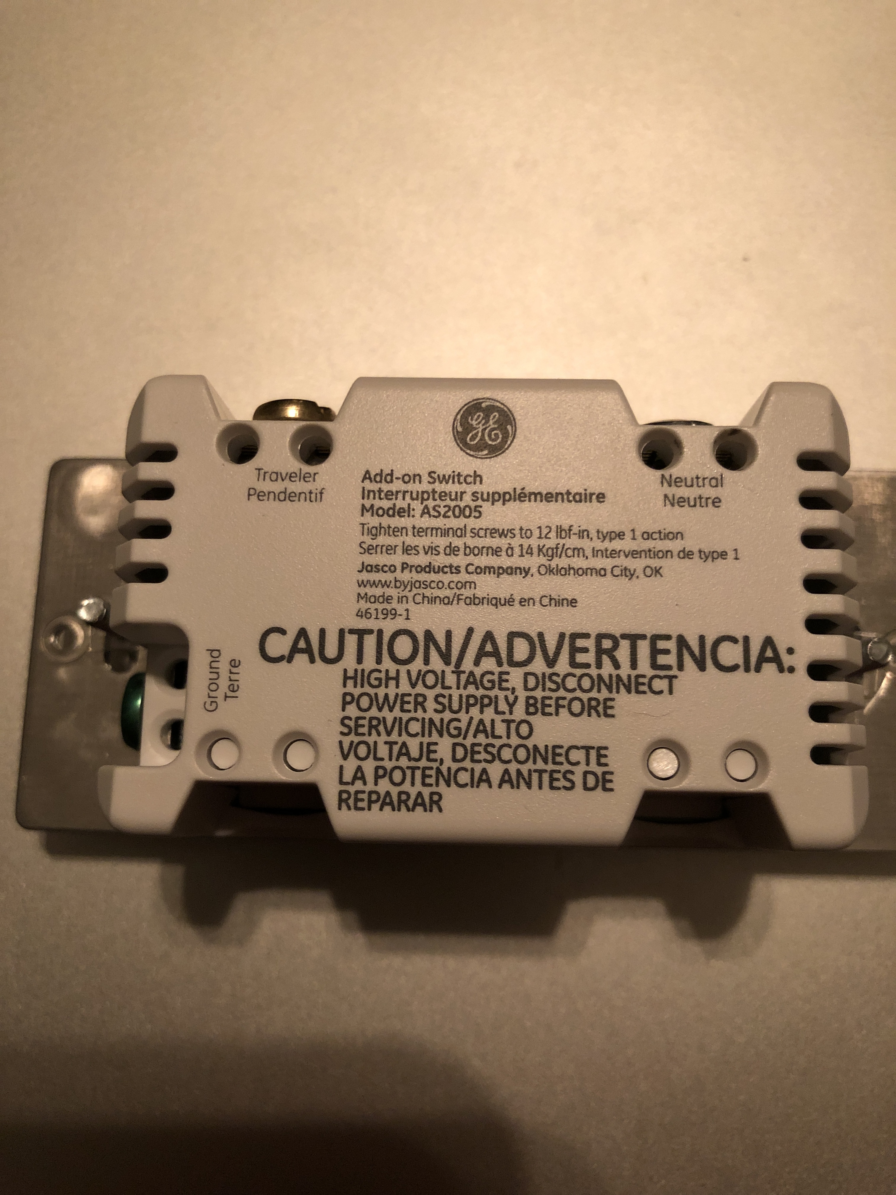
I’m using an Inovelli Red Series Dimmer and a GE 46199-1 Add-on.
I’ve triple and quadruple checked the connections. I’ve swapped out 3 different add-on switches, all same model. I was able to get it to turn every 15th time on the second add-on I tried.
I looked at the parameters in both the new and old ST apps. I had read the new app wasn’t properly saving parameters. So I tried saving them with the old app, via the ST IDE and directly on the Dimmer itself.
I’m at a complete loss. I’m using the same model add-on in a neutral 3-way application and it’s working great.
Parameters are set at Non Neutral for AC Power type or Zero in the IDE and 3-way momentary for Switch Type or 2 in the IDE. Parameters 21 and 22 respectively.
 with that all said. The first box mentioned above has a bundle of neutrals in the switch box. The second box above has no neutral bundles contained within the switch box and the last switch box above does have a bundle of neutrals.(two of the four switches in this last box are 1-way, one is 2-way and one is a 3-way).