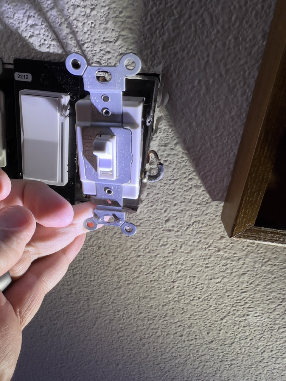
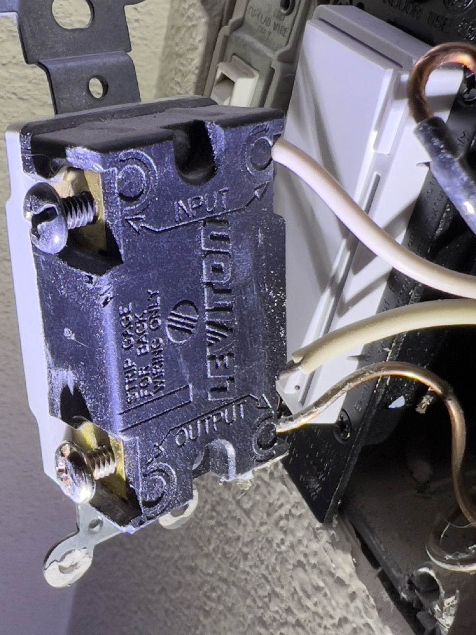
I am hoping to find some configuration I can use for my 4-way switch that I don’t think has a Neutral. It is currently implemented with a 4-way Leviton and I have two black wires and two white wires. One side of the switch in the back says input and the other output. (see below)
The dumb switches are that for now. Dumb. Line load and ground.
Is this configuration even supported? I think from what I have seen in the manual it would not be but I wanted to make sure. Then all that said, is there any thing I can do to make this work??
Happy to supply more information just not sure what else to add. Thanks in advance. These 3/4 ways are killing me in this older house with not a lot of neutral options.
I should probably also add that all wiring in the house is 12-2.
The first thing you have to do is to understand your entire configuration. How many switches are there that control the light(s)?
In multi-way configurations, there will be 3-way switches on both ends of the switch leg, with one (or more) 4-way switches in the middle. With a typical neutral configuration, power originates on one end at a 3-way switch. The power traverses the remaining boxes with 3-wire connections between them. You can have the line and load in the first box, or the line in the first box and the load in the last box.
If you’re lucky, you’ll have a neutral configuration. It is possible to wire a multi-way with a non-neutral configuration, which can get complex.
So to start, you need to inspect all of the switches in the leg and find the two 3-way switches on the ends and test to make sure you have a neutral configuration as I described above. If you have a neutral configuration, you’ll need to determine if you have a line and load in the first box or if you have a line in the first box and load in the last box.
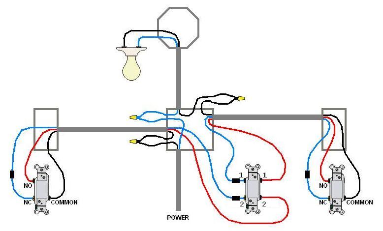
Take a look at the Inovelli 4-way wiring diagrams to help you understand how these work and help you determine what you have.
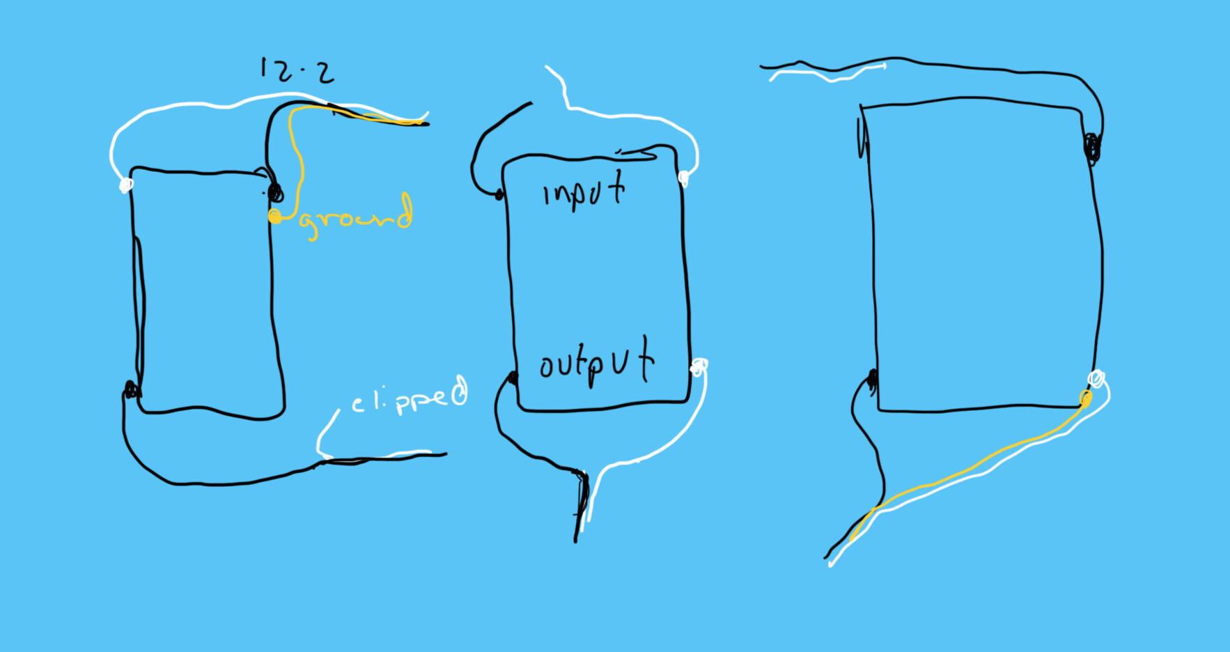
Thank you for your detailed reply. I looked at the other two outlets and I did see the three way switches. In each of the three way switches I had two 12-2 wires in each. In both of those the white wire was not used and just clipped. It looks like maybe the one that is clipped is acting as the red wire but I don’t see any other wires that are connected with wire nuts. None of the diagrams seem to match up with what I have if that’s the case.
Ok, so functionally, you have a 3-wire between the switches (two 12-2 with a conductor not used). From your description, it sounds as if there are not other wires “involved” i.e. connected in some way at either of the 3-way switches, so that indicates the line box is the 4-way switch box i.e. a 4-way power in the middle…
This configuration can be a neutral, or, I THINK, a non-neutral. You’ll need to look at the conductors in the 4-way box to determine this. With a neutral 4-way power to the 4-way box, you’ll have the two 3-wires from the switches and TWO 2-wires, one of which is the line/neutral and the other is the load. (I know you said there were lights between the switches, but the first one is probably being fed by a 2-wire connected to the 4-way switch box.)
I know your title says “No Neutral” but investigate the 4-way box to ensure you don’t have a line and neutral, looking for the two sets of 2-wires. This will be a bit tougher since all 2-wires are used. Identify the 4 going to the switches and eliminate those, and see what’s left.
I don’t think this has 3 or 4 wires running between the boxes. I think line comes in the left side via a 2-conductor from the lights and is fed through 2-conductor to the middle then right box then a 2-conductor goes back to the lights. If true, it’s not possible to get line, load and neutral to a switch in any one of the boxes.
Sorry for the late response here! Finally have some time to get back to trying to figure this out. I have looked in the boxes and do not see any other wires. I think this means I don’t have a neutral configuration. Just looking at the Wiring Configuration table am I right in my understanding that I can’t use a smart switch here? If not innovelli is there any brand I could use?
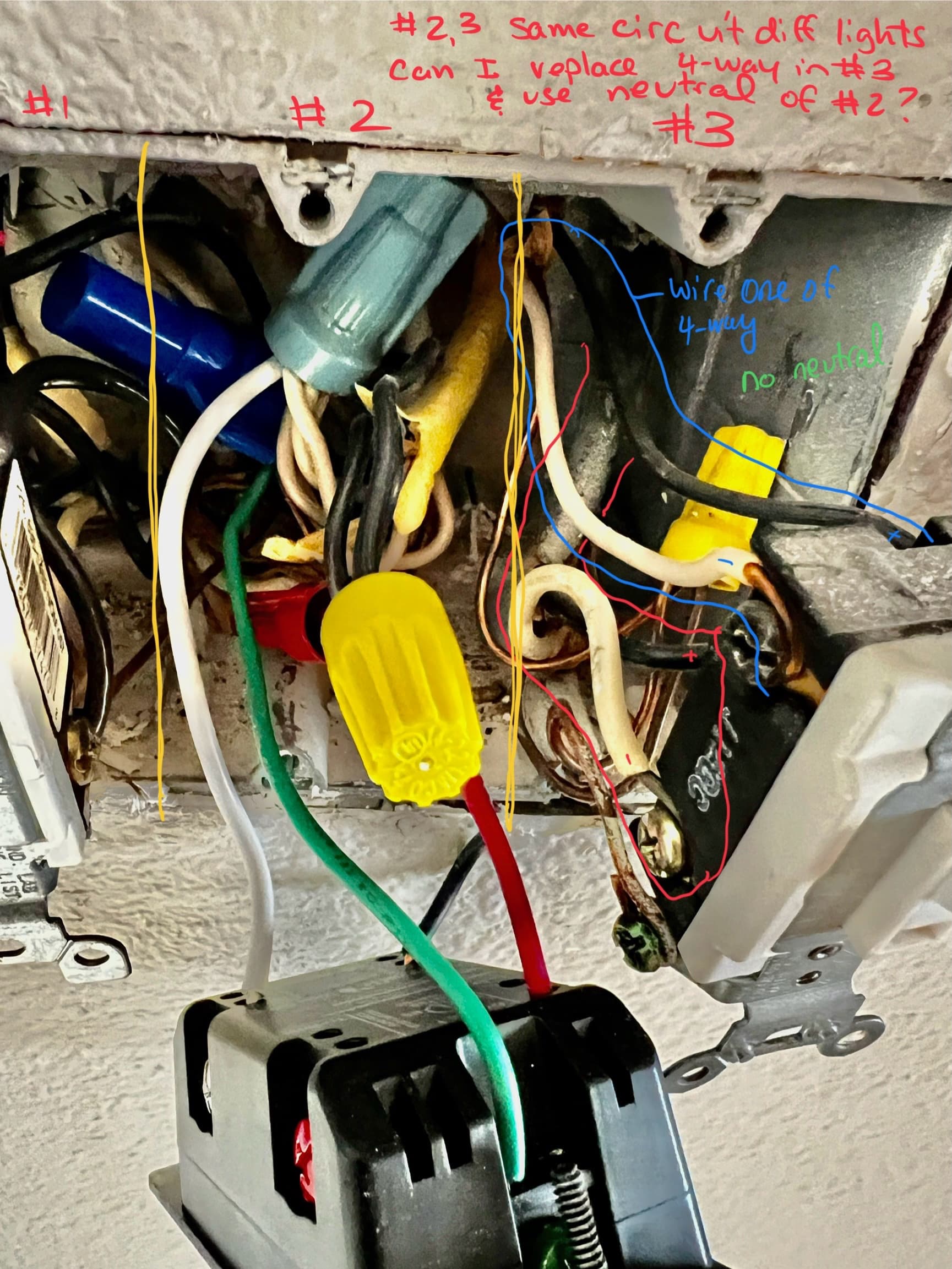
Below is a pic of the 3 gang. #1 is a 3-way with a detached garage and I think it’s also controlling an outdoor light receptacle. #2 is the foyer (hallway) single with Neutral. and # 3 is the 4 way Im trying to work out. You can see that it only comes in with a 12-2 for top and for bottom. #2 and #3 are on the same circuit though they control different lights. #2 has a neutral so does that mean that because they are on the same circuit I can tie into the neutral bundle in the box? There are more than one neutral tied together even though the only switch in there tied to it is #2. Im hoping if I can attach a neutral to #3 into that bundle then I can use the 4 way.
@Bry / @PJF,
Sorry to ping you on such an old thread but I was hoping to get your feedback on if the neutral bundle in the back of gang 2 can be tied into a 2-1 in a 4-way given #2 and #3 are on the same circuit?
As long as the bundled neutrals are all on the same circuit, it’s all good - in that case, just pigtail the other (new) switch’s (new) neutral into that existing bundle. In other words, do not peel off a neutral, etc.
Looks like that’d then be 5 neutrals under that nut, which can get dicey in terms of a wire inadvertently slipping out or getting pushed out of the nut. A 5-port Wago would be a huge win there.
Ok, so now Im looking at the diagrams and still trying to figure out how I can get this switch installed. None of the diagrams seem to match up much in my mind. On the 4 way I have an input and an output both of them have a black and white. I get the idea of just pigtailing into the neutral bundle but then I don’t know where to put the each of the other wires for the 4-way. Do I have line and load in same box or different boxes and how do I tell which is which.
Thanks for any additional insight you can provide.
I should also probably add, that I have the ability to have three 2-1 switches with two of them configured as Aux Switches and I also have two Aux switches that I can just use in the two 3 way switches. I’d think that the 2-1 gives me more options but at this point I just want the dang switch to work the hallway lights…thanks!
My local hardware didn’t have them but amazon will have them to me tomorrow. At the rate it’s taking me to figure out this dang light configuration, tomorrow will be just fine!
You’re going to have to figure out your wiring configuration. Don’t concern yourself with trying to match and existing diagram. Instead, work on diagramming the wiring connections between all three of the switches and the light (s). If you can provide an accurate diagram then we can provide you the proper diagram modified for either an Inovelli and two boxes or three iInovelli’s.
Depending upon your knowledge level, that alone may be a difficult undertaking. You might wish to consult with an electrician to help you.
Thank you. I thought I had created the diagram earlier in the thread and was trying to figure out if I had a neutral or not. I see now what Im missing is where the lights are in relation to each switches on that diagram as well so I will work on making a better diagram. Im hopeful Im knowledgable enough to figure out the configuration, guess we will see.
So 4-way box has line and neutral but it appears one of the other boxes has the load. You need 3 conductors going to that box to wire it using aux switches.
Using 3 switches run line and load from that box to the other 2 boxes. Connect load wire in the box that has the load. Can’t tell if it’s left or right in your drawing, but id guess right where wire goes out top of box.
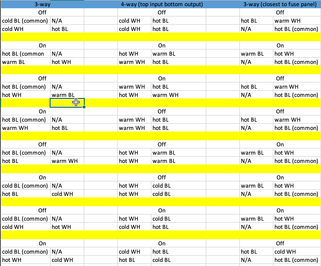
Thank you very much for your help so far @PJF . I’m trying to parse your response but not sure Im tracking. In order to try and gain more clarity, this morning I pulled all the switches out so I could test for voltage using AC voltage detector. I tested for voltage in all the configurations I could think to test and noted each of the switch’s terminals. I noted which of the three ways boxes the power is going into (confirmed by peeping in attic). My voltage tester beeps really fast, regular speed or not at all. I refer to those states as hot, warm and cold. I have inserted that table below for reference. I think the 3-way on the right is where line is.
To restate my hopes for the final state. Since I have all smart lights, I am looking to have three switches that all have power and are configured in smart light mode. I don’t need the three switches to necessarily work like a traditional 4-way circuit as I can program them to work as a group and to turn the lights on and off. Given that, Im looking for a configuration that would let me do that. I had a 3-way you (PJ) had given me help on doing basically the same thing (link to post)
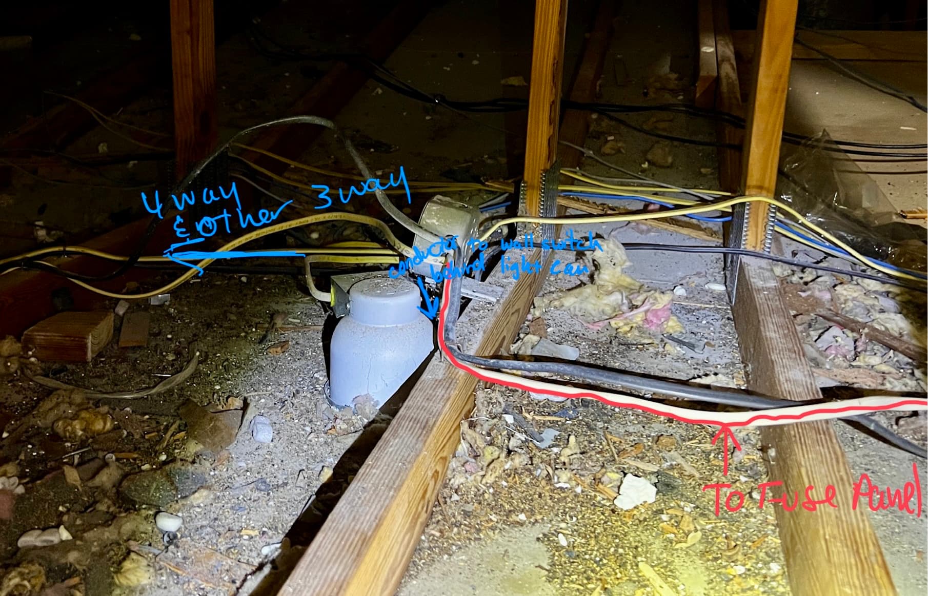
Would it be possible to have the switch box on the right be a 2-1 switch that controls the light and load and then have power to the other two switches to just act as smart switches similar to the post referenced above? I got in the attic to see what I could see and took this pic. I think it would explain why I don’t see all the wires Im thinking I would see in the box with the line in it according to the 4-way diagram.
Looks like power comes into the right box closest to the fuse panel and exits to the light from the left box. In the picture it looks like the wires might all come up to a box in your attic. I just can’t tell enough to tell you how to wire it. If you map out which wires go where as in the romex and how many conductors they are then it might be possible to suggest something.