Red and Aux 3 way install Help

I have a 3 way with no neutral and want to setup with the red dimmer and a ge aux. I have previously bought lots of switches and dimmers from 2018 sale and not installed as we were possibly moving. When i went to install a regular inovelli on/offswitch i found that there was no neutral in this switch box. Anyways i just wanted to confirm that this wiring scheme will work when it is power, light, switch, switch 3 way with wiring scheme with the new no neutral setup. Also it is track lighting with 6w X 13 lights so i meet the minimum load also.

Yes you would follow the below diagram. Also be sure to set both Parameter 21 and 22 for your setup type. Just ignore the wires to the 2nd aux switch in the diagram.

John

Also my load is a track light with 6w led mr16 bulbs non dimmable. Assuming a red dimmer set to 100% brightness when on and ramp rate set to 0 should work pretty much like a on/off switch and not cause any issues with non dimmable mr16’s?

I can’t say but my guess the LED’s might not like it.

But you might look at replacing the Aux switch with a dumb 3-Way. This would eliminate the possibility of accidentally dimming via the Aux switch.

That’s not even close to correct. The OP has a power to the light 3-way with no neutral in the boxes scenario and you posted a diagram for a power to the box 4-way with neutrals routed.

That is the proper wiring diagram for a power to the light 3-way using dumb switches. At least one other poster in this forum had the exact same power-to-the-light scenario and wasn’t able to get the switch working properly. Additionally, if you look at the wiring examples listed on the Inovelli instructions, they don’t show any power-to-the-light wiring schemes.

I would consult with Inovelli to see if their switch is supported with this wiring scenario.

https://inovelli.com/wp-content/uploads/LZW31-SN/Wiring-Guide-Dimmers.pdf

I understand that the situation is not identical, however in the diagram I posted the neutral was not connected to the Inovelli (for whatever reason) so the wiring is basically the same.

This sounds like the situation I wired up last weekend.

In my situation, I put the 3-way dimmer in SB2 in OP’s image, and the Aux in SB1.
The Line from the light went (through the SB1 box) to the Line in the 3-way dimmer AND pigtailed into the Neutral of the Aux.
I connected the white/Load from the dimmer to the Load coming from the light.
The red/Traveler from the dimmer went to the Traveler in the Aux switch.

Set the Power and Switch Type parameters (#21 & #22) to Non-Neutral and 3-way Momentary (or Aux depending on your UI)

Disclaimer: I’m just a noob.

Can I get an official @anon64478871 response about my setup? Will receive red dimmer today and got my he aux yesterday. Thanks

I found the diagrams on this website to be helpful… I think you want to look at “Method 5” and Solution D-5 which would support Inovelli dimmer only. Worked for my setup. good luck.

http://azhb.com/how-to/three-way-switch-how-to/

@JohnRob is correct about the setup. Follow his lead :slight_smile:

From your description, the diagram in post 2 will work. If when you start looking at you actual wiring and find something different or something that doesn’t make sense to you pls post what you find.

BTW I am not a part of Inovelli. Just a guy who has too much time on his hands and went through sorting out my own multi switch installation recently :slight_smile: I also did a lot of old house re-wiring when I was in college.

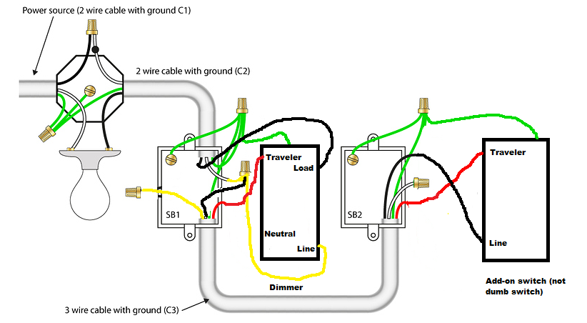
When using the dimmer with an add-on switch (not a dumb switch) and no Neutral, you should hook up the wires like this:

Dimmer switch:

Port on Switch Wire to connect
Line Wire that is always live
Load Wire that goes directly to bulb
Neutral Empty
Traveler Wire that goes to Traveler port on Aux switch

Aux switch:

Port on Switch Wire to connect
Line Wire that is always live
Traveler Wire that goes to Traveler port on Dimmer switch

Its essentially the same thing @JohnRob posted. I modified your original picture to help clarify. Pretend the yellow wire is actually white:

1 Like

I just want to confirm what people are saying as i have it apart now and it does not make sense. So my original picture i posted, the blacks are wire nutted together from the 14/2 and 14/3 and the white from the 14/2 is the line (hot). This is all working with 2 dumb 3 way switches, exactly as shown in the picture. I am now supposed to take the white hot from 14/2 and connect it to the black from the 14/3? And then nut off the the other white from the 14/3 and then finally put a 3rd wire nutted to the 14/2 white and 14/3 black to the line on the dimmer?

Well i got brave enough and tried what JT and johnRob were saying above and it worked perfectly once I finished wiring i changed option x12 and x13 on config switch so it was set to no neutral and aux switch and everything works perfectly. Thanks for such great support. Going to be doing the rest of my gen 1 switches, dimmers now, they all have neutrals so should be easy to do. Thanks

@Rob79 - I hope so because that wiring was a $h!tshow…