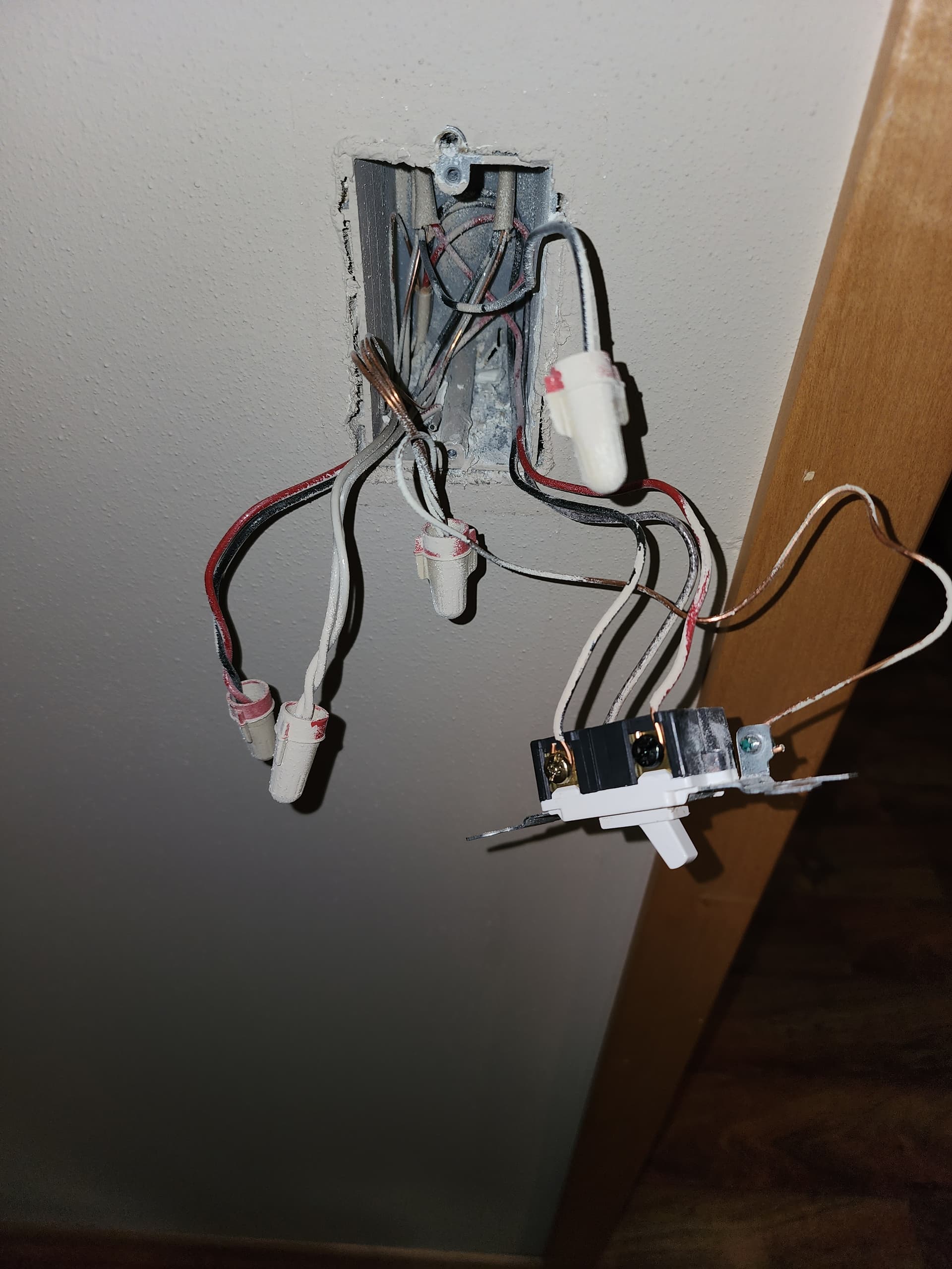
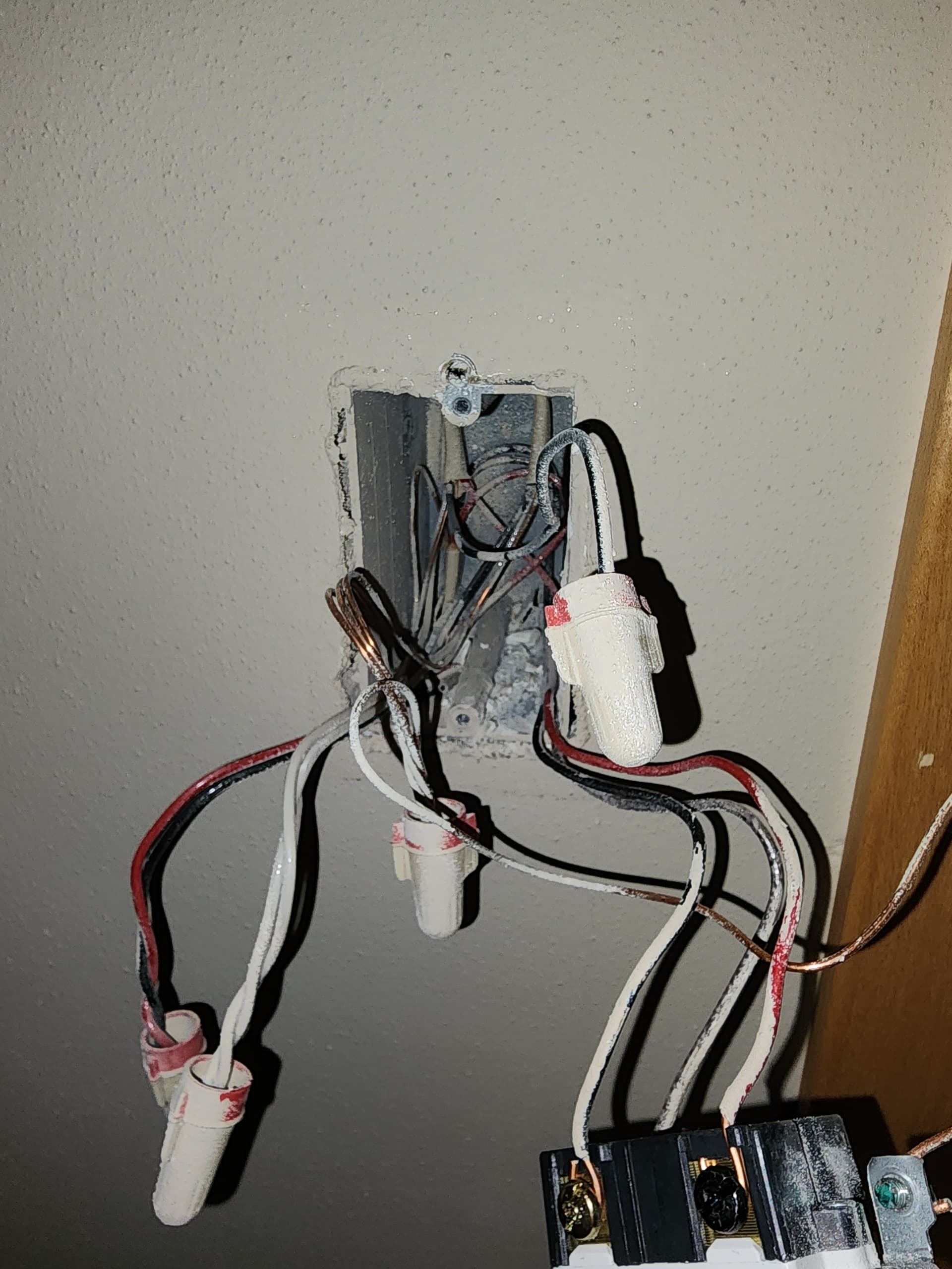
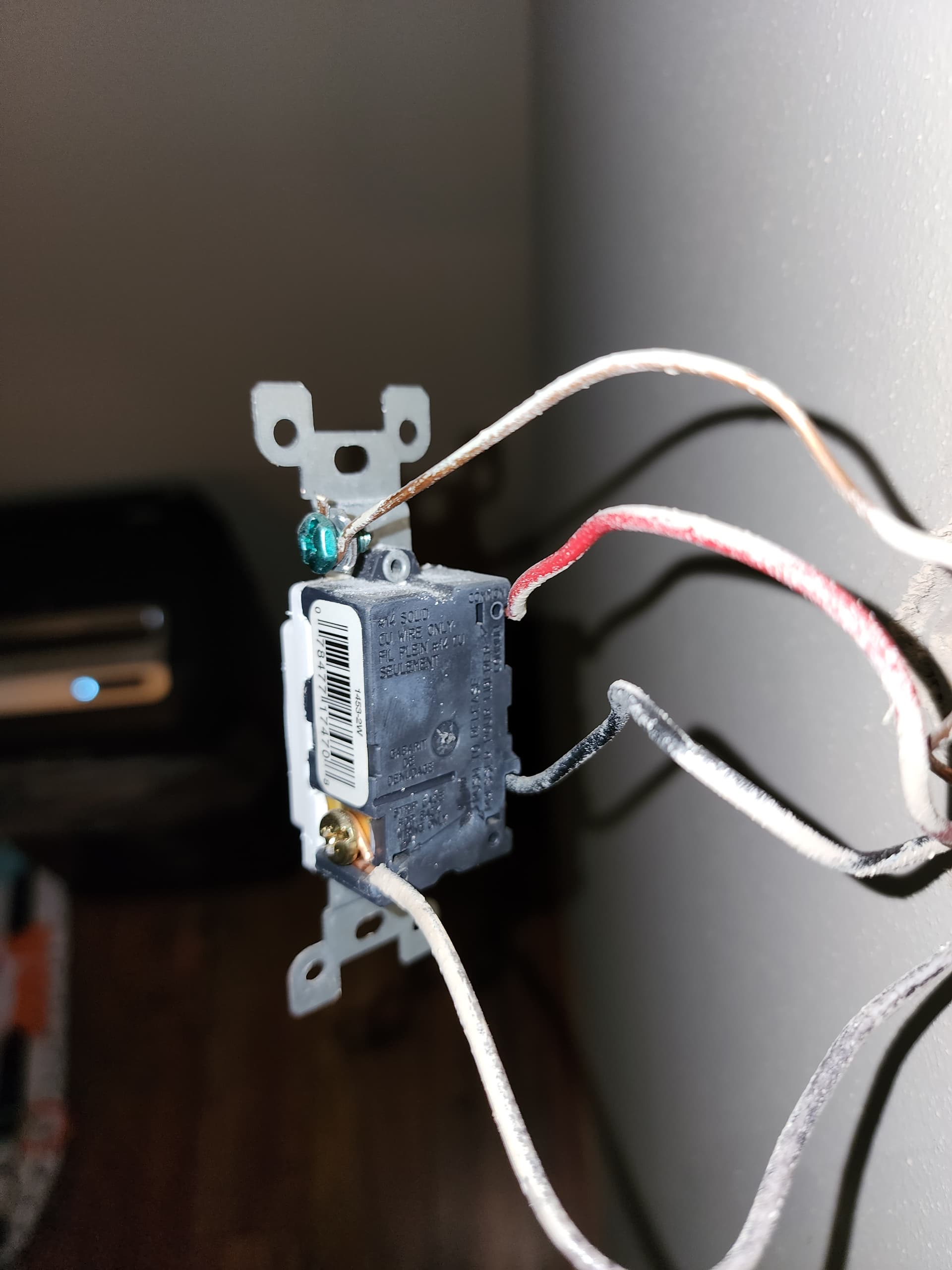
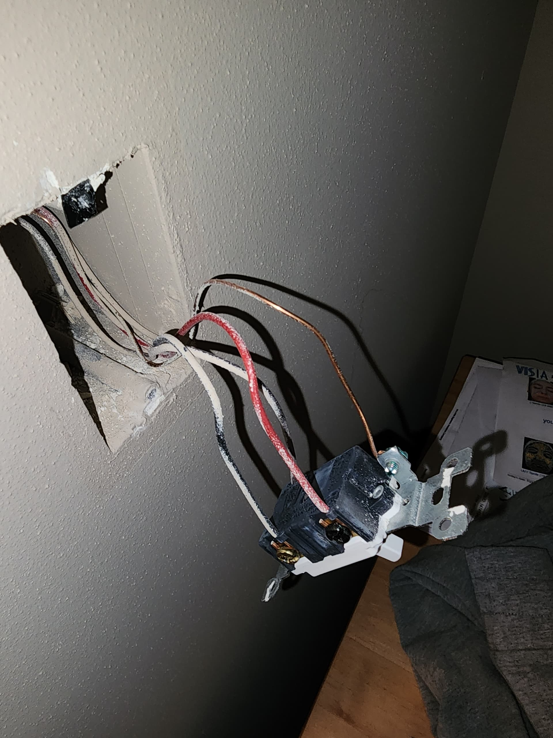
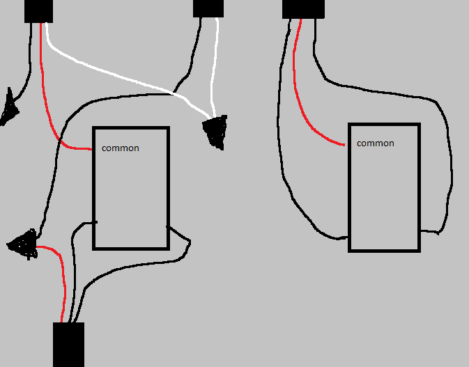
A few issues throwing me off are that in my wiring the red wire goes into the screw marked common on both switches. Also, I seem to have one black wire that remains unconnected to anything else.
I should probably call an electrician, but I think I will have a hard time having one come out to install a single switch.
Model: Smart 2-1 Switch (VZW31-SN)
Neutral or Non-Neutral Setup: Unsure
How is your switch wired: 3-way
Multi-Switch Setup: dump/existing light switch
Pictures:
I looked at your drawing but did not confirm against the pictures, as the drawing makes perfect sense. So my comments are based solely on the drawing.
The LEFT box with the 2-wire and 3-wire is where the power originates, coming in over the 2-wire. In that box, the unswitched hot is sent to the RIGHT box over the RED conductor.
The RIGHT box now has an unswitched hot on the RED conductor. That hot is returned to the LEFT box switched using either the black or the white conductor, depending upon the position of the switch.
Back at the LEFT box, the two switched conductors from the RIGHT box are attached to the NON-common terminals.
The switch hot to the light is going out of the LEFT box over the other 3-wire. Usually it’s a 2-wire to the light, but a 3-wire is perfectly acceptable. In your case, the switched hot is going over the RED conductor to the light, which is why the black is unused. The white on that 3-wire to the light is used to send the neutral.
Are you planning on keeping the dumb switch in the RIGHT box, or switching out for an Aux?
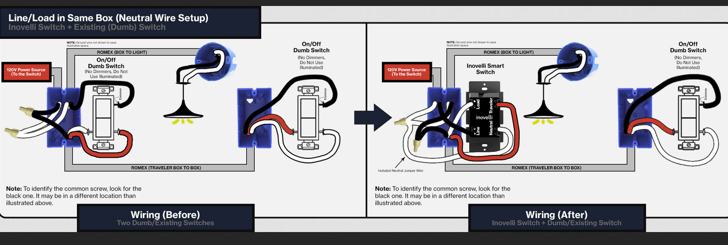
The RIGHT box is where the dumb switch goes. Here is the proper wiring diagram. It will probably be easiest for you to understand the flow if you move the conductors on the dumb switch to match the drawing.
However, remember that on the load side, you are feeding the switched hot with the red on the 3-wire, not the black. Leave the red as the feed so you don’t have to re-wire at the light.
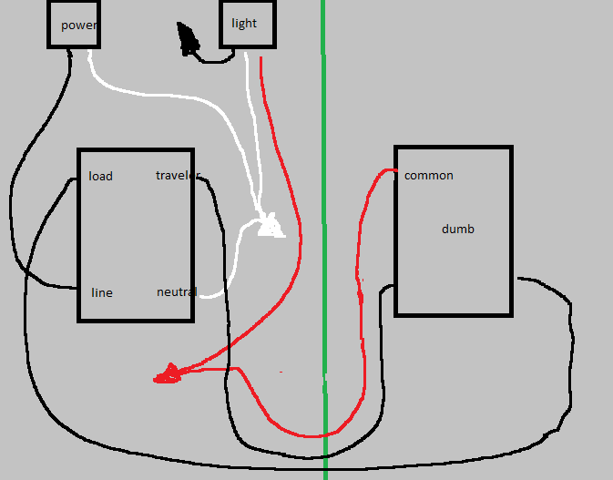
I appreciate your detailed explanation. If I understand correctly I believe this new crude ms paint drawing will show the updated wiring with the new Smart 2-1 switch. You recommended updating the conductors to match the diagram, but I was worried I would confuse myself so I stuck with the original conductor setup.
Hopefully I understood this correctly, because the two red conductors matching up is pleasing.
After wiring the switch as discussed I ran into an issue where using the Dumb switch worked correctly, however turning the light on using the Smart 2-1 switch cause the light and switch led to flicker continuously.