Long time listener, first time caller. I’ve successfully installed about 15 Red switches and dimmers around my house, in Single Pole, 3-way and 4-way setups. Most I was able to get to work either right away or after singing configuration a few times.
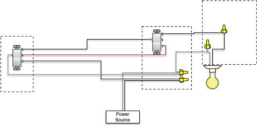
However one is not really behaving and I wanted to get your thoughts. It’s a 3 way configuration with load in one box and line in the other. I have a dimmer hooked up with line going into it, then 2 wires to the other 3-way and then up to the light. There is neutral and it’s connected. To the best of my knowledge this is what my wiring looks like:
Load Center ----- Dimmer ======== 3-way Switch ---- Light
When the 3-way is flipped up, the dimmer acts normal, like it’s supposed to. However when it’s flipped down, the dimmer just shuts off (or blinks red), when I flip it back up, the led bar cycles all the colors like it’s a boot up.
If I interpreted your description correctly, this indicates that your dumb switch is controlling the power going to the dimmer, which it should not. As Ma2J suggested, a wiring diagram is needed to figure out how to fix it.
Also, a question for you: was your circuit working correctly as a 3-way before you installed the dimmer? Just checking, because sometimes people don’t know how a 3-way is supposed to behave. When the dumb switches were in place, if sometimes you flipped one switch and nothing happened until you flipped the other one, then the wiring was wrong. And if you merely move the wires from the old switches to the new ones, then you still are working with incorrect wiring.
Good points, all of them. The circuit worked fine before the change and there are other 3-ways in the house. They work well with original as well as inovelli switches.
The putting dimmer on the wrong side was my first thought as well, but I did check with a multi-meter and the “Line” wire stays at 120V regardless of how I flip the dumb switch.
If I look at the switches in the diagram closely, I can see a green screw, two blue screws and a brass screw on each switch. Based on my experience, I’d interpret the green screw to be for the system ground, the brass screw to be the common terminal, and the blue screws to be the screws for the travelers.
Now, either your diagram is an accurate representation of your wiring, or it is not.
If it is accurate, then there’s a big problem because you’ve got power-carrying wires connected to ground screws. If the ground screws are also connected to the system ground and they should, then your breaker should trip immediately, and nothing should work, at all. But that’s not what you reported. If the ground screws are not connected to your system ground, then you’ve got floating voltages that could kill you but I don’t see how you’d get the behavior you reported with the circuit you’re showing. Which suggests the diagram is in fact not accurate, in which case…
If the diagram is not an accurate representation, then I cannot diagnose the problem because I’m looking at something that does not correspond to the real wiring.
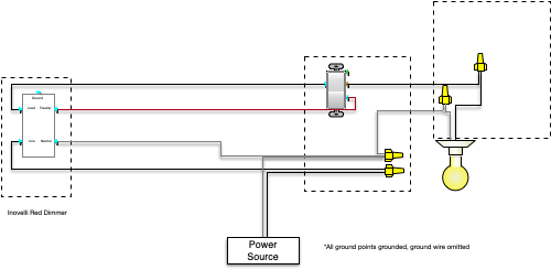
The diagram is not accurate in that way, I was trying to reuse the connection nodes in the diagram. I did hook up ground correctly. Let me try to come up with a better way to represent it. Bear with me.
A setup wired like the diagram you show should work. In particular, there’s nothing in that diagram that would explain how the dimmer would ever lose power.
Note it was a bit hard to make out the text in the Inovelli switch. I think your image gets shrunk along the way so I had to blow it up quite a bit, and the text was very blurry. I don’t think there’s a high probability I misread something, but that probability does exist.
You mentioned having tested the line wire going to the Inovelli switch. How did you test it?
The only other thing I can think of is to factory reset the Inovelli device just to make sure it hasn’t kept some setting that was used in testing. (If you read the documentation carefully Inovelli mentions at some point that if inclusion in the ZWave network does not work, it may be because the switch was included in a testing network but never excluded after testing was done. So it seems there’s a precedent for devices having been shipped while still being set for testing.) Try again after that.
Line testing was done my a digital multi meter, put the ground lead to the ground terminal and tested at the line screw.
Good point in trying a reset. Will try that next. I am also surprised as I have others working fine as well. Have another shipment of dinners coming in, might also try replacing the dimmer with a different one.
Yea, I’m not seeing an issue with the diagram you’ve presented. Especially if the dimmer electronics is getting turned off by flipping the dumb switch. Doesn’t make sense to me. You did say the line is active no matter what position the dumb switch is in, correct? I know you said you had other 3 & 4 ways working. By chance did you forget to configure the handler for Neutral and 3way with a dumb switch?
If the factory reset doesn’t work, I’d be curious to see what happens if you were to take one of the dimmers from your existing, working, 3-ways and swap it into this circuit. Then put this dimmer in to the known good circuit.
i’m sure you’ve done this… but make sure the innovelli is programmed to parameter 12 = 1 (neutral), and 13 = dumb switch 1. i had one of my three not working and found that somehow these 2 parameters were set up wrong. so worth a double-check.
Curious… Was this an existing circuit previously with two dumb 3 ways?
Reason I ask is it’s confusing why that many conductors we’re running between the boxes to start with, or did you run an additional wire?
If they were both dumb switches and both line and load were in the same box, my understanding is that the “usual” way to add the 3 way is to run a 14/3 (3 conductors + ground) and black tape the white wire since all 3 are hot. Your diagram had a fourth conductor running between the boxes… Just wondering if you added a new run or if it was there and unused for some reason?
All right guys, I finally got a chance to try everything and have solved the issue. The problem ended up a bad connection on the neutral line. Below I’ll outline what I’ve tried and saw so that it may help anyone else in the future.
As recommended above I tried replacing the dimmer with a different one, I only had a switch available so I used it. Once power was applied to it it started clicking and acting badly. I checked the voltage and saw that while line had 120v, and load had 0, the neutral had 70V(!), this led me to trace the neutral and see that it came off deeper in the gang box. Installing the neutral correctly, both the dimmer and switch ended up working correctly. So, moral of the story, check your neutrals people.
To answer some other questions from the thread:
to: harjms - I did test power in both positions, and was able to identify the line as well as both travelers
to: Barry - I did set the parameters for neutral and 3-way … those three me for a loop with a few of my first ones installed but since then I remember to set them every time
to: pbennett - The gang box for that remote switch has 4 other unrelated switches and also has neutral and that’s what I drew as a separate line … so there is a 3 wire romex and then neutral as well as neutral from other lines
Thanks to everyone and especially @ldd for helping me out.