The wiring in my house for the three way setup seems simplified and not follow the two wires configuration.
The current existing setup:
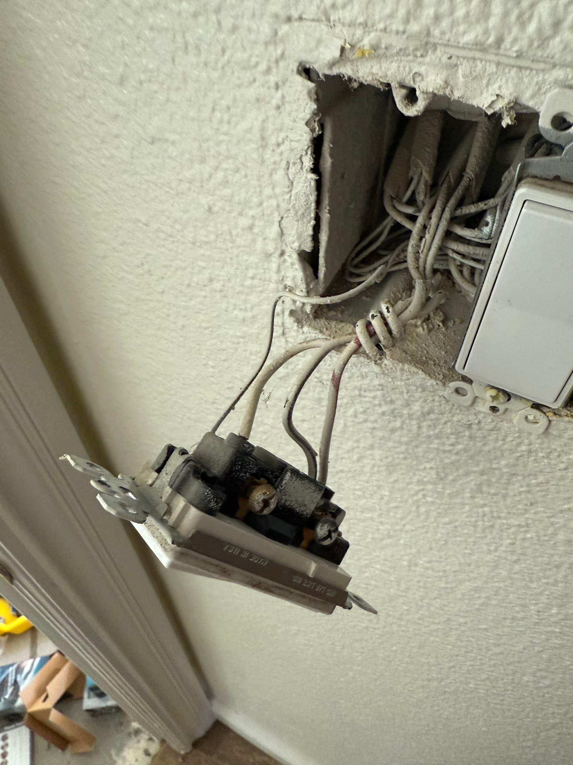
Switch 1 's wiring coming from two major cable and black wire from 1 cable, and white and red come from another cable.
the switch 2’s wiring only coming from 1 cable.
Not sure whether this is a blocker for continue using the white series. I’m planning to use two Inovelli switches for this Three way configuration, is it possible? Thanks a lot!
Model # of your smart switch: White Series Dimmer
Please provide whether or not you have a neutral wire – YES
3-Way: How is your switch wired?
3-Way = Two Switches to one Load
Multi-Switch Setup (ie: 3-Way, 4-Way, etc): Three way
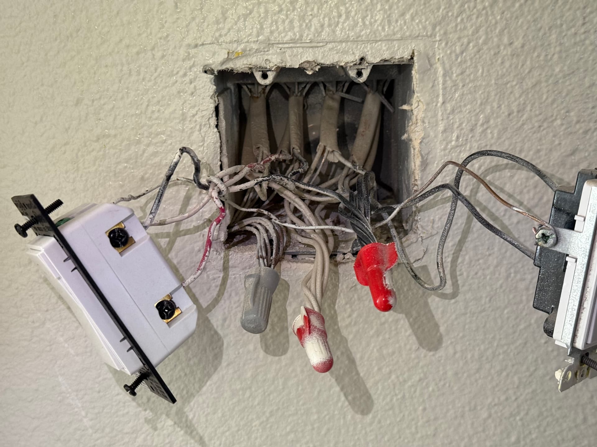
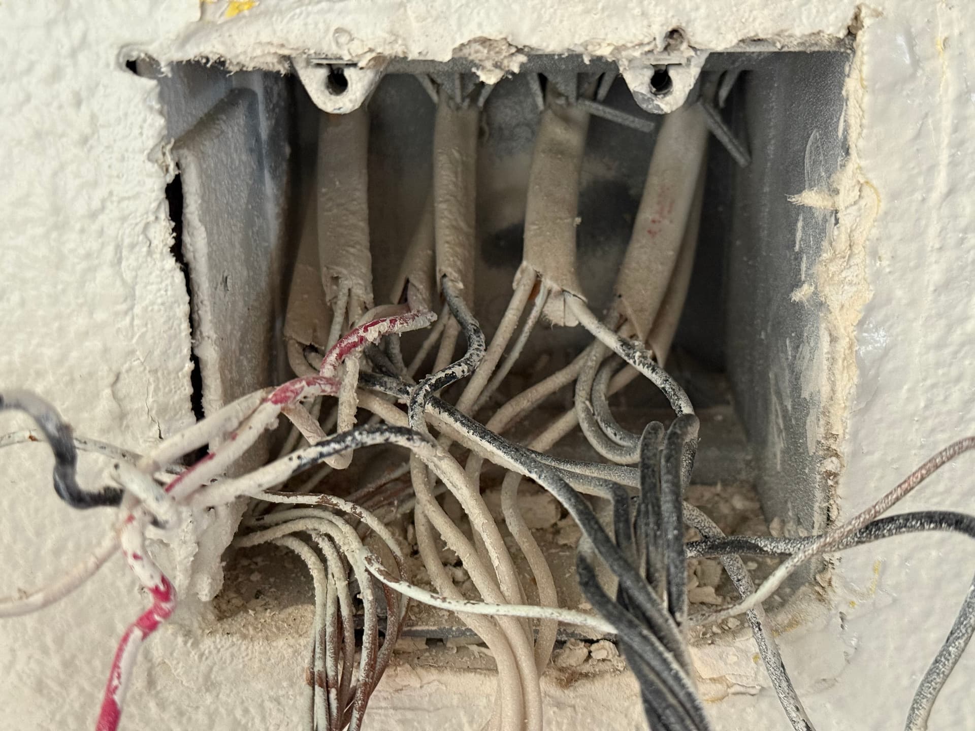
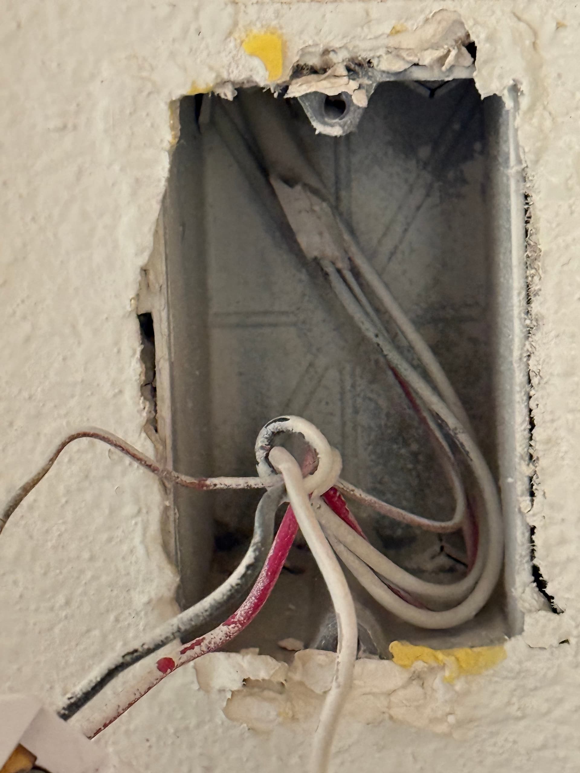
As @Bry would say, we need some better pictures to figure out what is going on. We’ll need to be able to see all of the wires inside the box and where they are going (what bundles are they attached to, etc) for both boxes to be helpful here. You will need to pull the right side switch forward on the box with two switches so we can see what is going on. If there are any wire caps back there get them so what we can see what goes where. Also if you can get some of the paint of the wires off so that we can see what color is what that would help a lot.
I suspect I know how this is wired but without seeing more there is no way to know.
Still not very clear. The third wire (black) that connected to the 3 way switch with the red and the white… where does it go? The 3rd wire (black) in the romex bundle with the red and white coming from the switch where does it go?
I’m kind of confident I see what is going on here. It appears that they used single pole switches to imitate 3-way switch functionality.
At switch 1 the single black wire tied to the switch that is going to, call it main wire 2, is more than likely the light fixture.
Switch 1 wire 1 that has red and white coming from it, red and white are used as mere travelers, while the black from that loom is pulling mains power and sending it to the secondary switch first.
Switch 2, black wire is line, and red and white are travelers back to switch 1.
What type of 3-way are you looking to make? Smart + Dumb? Smart + Aux? Smart + Smart?
My original plan was to use all smart switches so I have purchased a lot of them.
In current situation, I want to understand my options.
Smart + Smart > Smart + Aux > Smart + Dumb
So you have two possibilities, now that I see the other box. The first is that the line and load is in the double gang box. The other is that the lights are in between the two boxes.
If it’s the former, you will be able to use smart switches in both locations, as it will be easy to send a hot and neutral over to the single gang box. However, if it is wired with lights in between the switches, it will be difficult if not impossible to wire into smart switches without doing some rewiring in the ceiling.
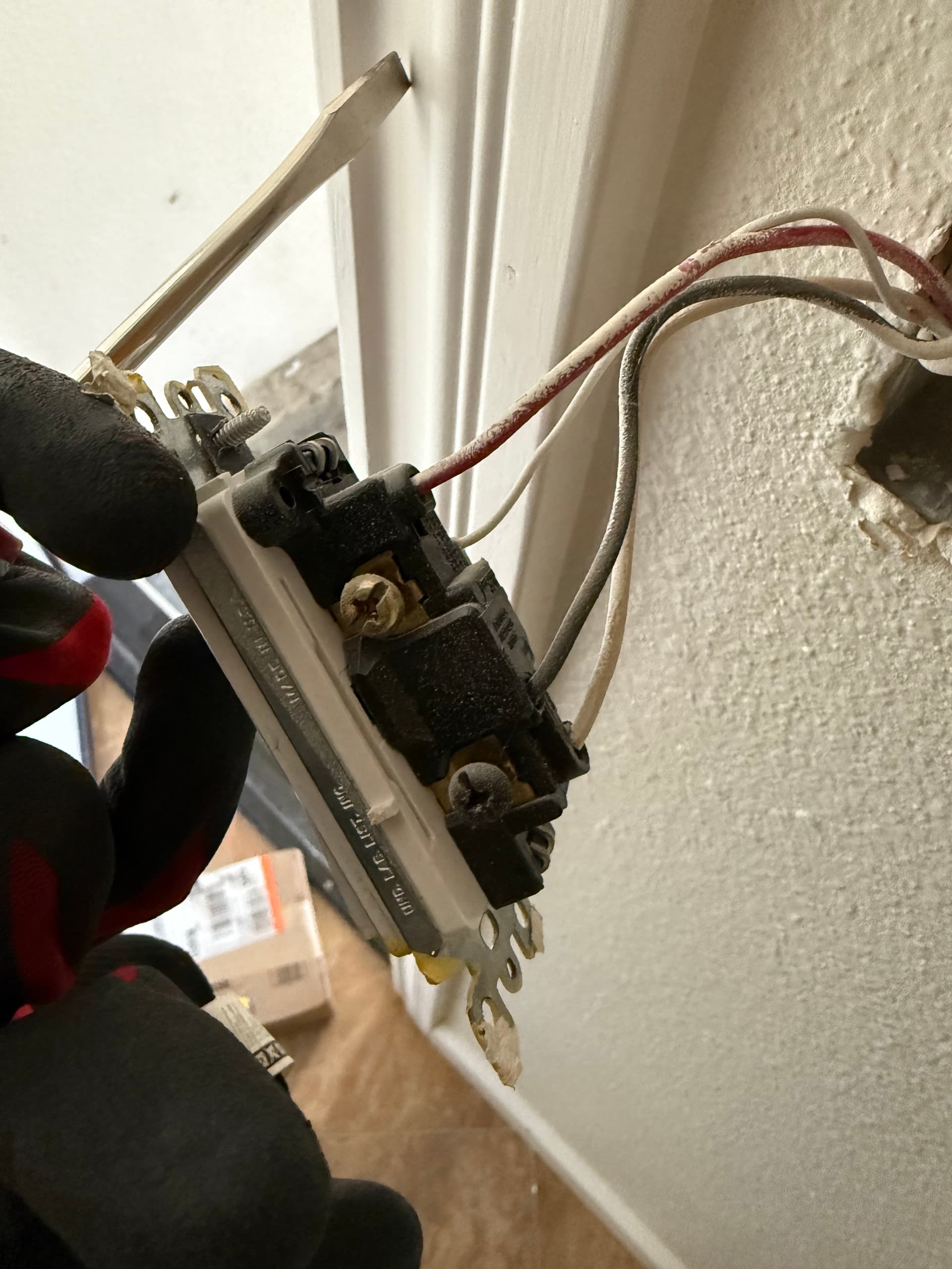
Unfortunately, I cannot fully discern your wiring to topology in the double gang box, even with the better pictures. I THINK you are trying to wire the left switch, correct? Unfortunately, when you took the additional pictures you swapped out the existing dumb switch for an Innovelli, so I can’t see the connections to the dumb switch, which are important to help figure out what you have going on.
If you want to take more pictures with that dumb switch properly reinstalled and working, I’ll take another look. That box has a crazy fill which makes it extremely difficult. It also doesn’t help that your painters did not stuff the box before they decided to paint every conductor white.
If you can trace the wires that I asked for in my previous post then I think I can help you. However you will probably need some wire nuts, a wire stripper and at least one 14AWG jumper wire (say about the length of the white one supplied by Inovelli and ideally black).
What hub are you using? (Apple Home, Home Assistant etc). If you want to go smart/smart then with the current state of matter binding you will be using automations to sync the two smart switches. Personally I would probably use an Aux switch based on what I am guessing since it needs no automation to work in your configuration though I need to know what wire goes where to confirm it.
To make this simpler, this what I am guessing you will see…
At the dual-gang box end:
The black wire from the original 3 way switch will go to one of the 2 conductor + ground Romex bundles. The white wire from the same bundle will go to the bundle of white wires with the red wire cap.
The black wire from the 3 wire + ground Romex bundle that has the white and red going to the 3-way switch will go to the bundle of black wires (with a different red cap).
If that is all correct then I think we can have a pretty good guess of what is going on.
If you have a multimeter. Pull the black from the switch in the single gang box. If you lose the lights and that black wire has 120v on it and the rest on every lead has zero then your input is wherever that black wire is tying into in the 2 gang.
To make it a smart to smart switch, you want to pigtail from that line supply to the smart switch, then the single black is your light fixture.
To supply the secondary smart switch keep that current black tied into the line supply to feed out to the second box. Cap the red.
In the 2 gang tie the white neutral to all the neutrals in the back of the box
I can explain better over video if necessary CroVlado on discord
I’m afraid you are going to have to make changes to the wiring layout in one or both of the boxes for any of the three possible configurations. The changes are pretty simple and I can give you a “step by step” if you pick which of the three configs you want to do. You will need a short 14AWG jumper (ideally black but it does not really matter) plus the jumper that Inovelli supplies and some wire nuts for any of the options however. BTW If I run out of jumpers I typically just take a length of 14/2 or 14/3 ROMEX cable and chop a piece of the end of it and strip it.
Oh I’m not worry about wiring layout in the box, I don’t want to open the wall and add additional wire. If Smart+smart need automation to sync then I will go Smart+Aux. Is that what CroVlado suggested?
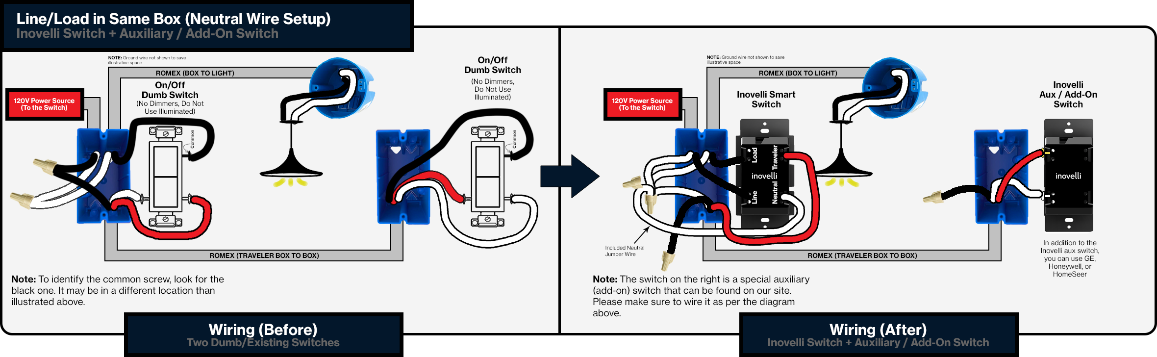
Based on our data regarding the wiring this how I would implement it:
At the dual-gang box end:
Connect the White wire that went to the 3-way switch and the white jumper wire supplied by Inovelli to the existing bundle of White wires (that will allow us to send a neutral to the single gang box and give us a neutral for the smart switch).
Connect the other end of the Inovelli White jumper wire to “Neutral” on the smart switch.
Connect the Black wire from the 3-way switch to “Load” on the smart switch (that is the power leaving the smart switch to light the bulbs).
Remove the Black wire that was going in the ROMEX bundle to the other box from the bundle of Black wires and cap it (we will not be using it).
Add a jumper to the bundle of Black wires and connect it to “Line” on the smart switch (this provides continuous power to the switch).
Connect the Red wire that went to the original 3-way switch to “Traveller” on the smart switch (this will receive the signaling from the remote Aux switch).
At the single-gang box end:
Remove the Black wire and cap it (we will not be using it)
Connect the White Wire to “Neutral” on the Aux Switch
Connect the Red Wire to “Traveller” on the Aux Switch
You then need to program the smart switch as “Multi Way(Aux)”. The instructions are in the card that came with the switch.
@andrewk The Aux arrived and it works without issues. Thanks a lot!
I have another scenario need your help if you could help to review.
Basically the light is not in between but connect to the single non-power location. And I realize that I cannot use aux at non power side since there is a black wire goes to light and one black wire and a red wire to get power from another location. Is it possible to use smart-smart for this use case? Currently I installed both location with smart switch but only when I turn on power side and then turn on non-power side then light can be on.