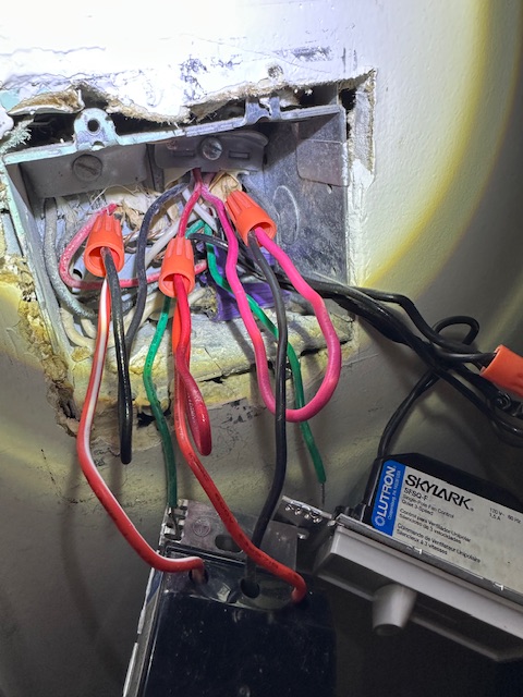
We have a fan and light combo in a room. The fan works on its own switch and the light is on a 4-way circuit. The electrician that originally installed this did something that is confusing me. In the first photo you can see the feed wire is a pinkish red wire going to the black wire of the dimmer switch. Then red wire to red wire going up to the light and red/white wire of the switch to the black wire going to the light.
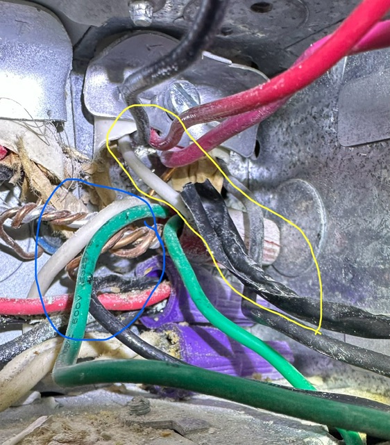
The second photo I circled the neutral wire in blue that comes from the line in. It’s bundled together with some other white wires. The first problem that is confusing me is the white wire wrapped in electrical tape circled in yellow. That wire is connected to the fan switch. So as far as I know that is feeding power to the fan. So for this box how am I wiring up the main inovelli switch?
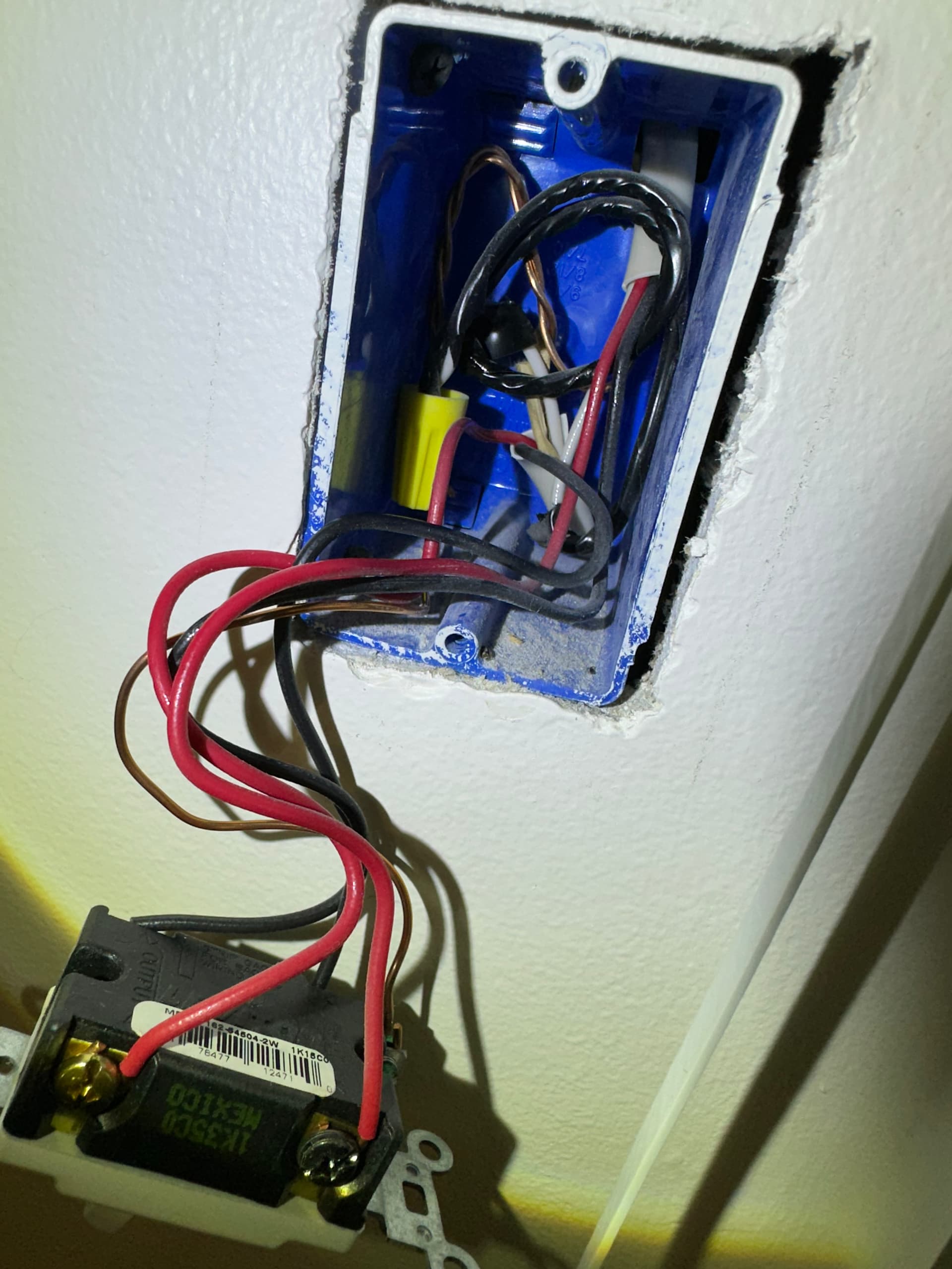
In this photo the electrician used the electrical tape on the white wires
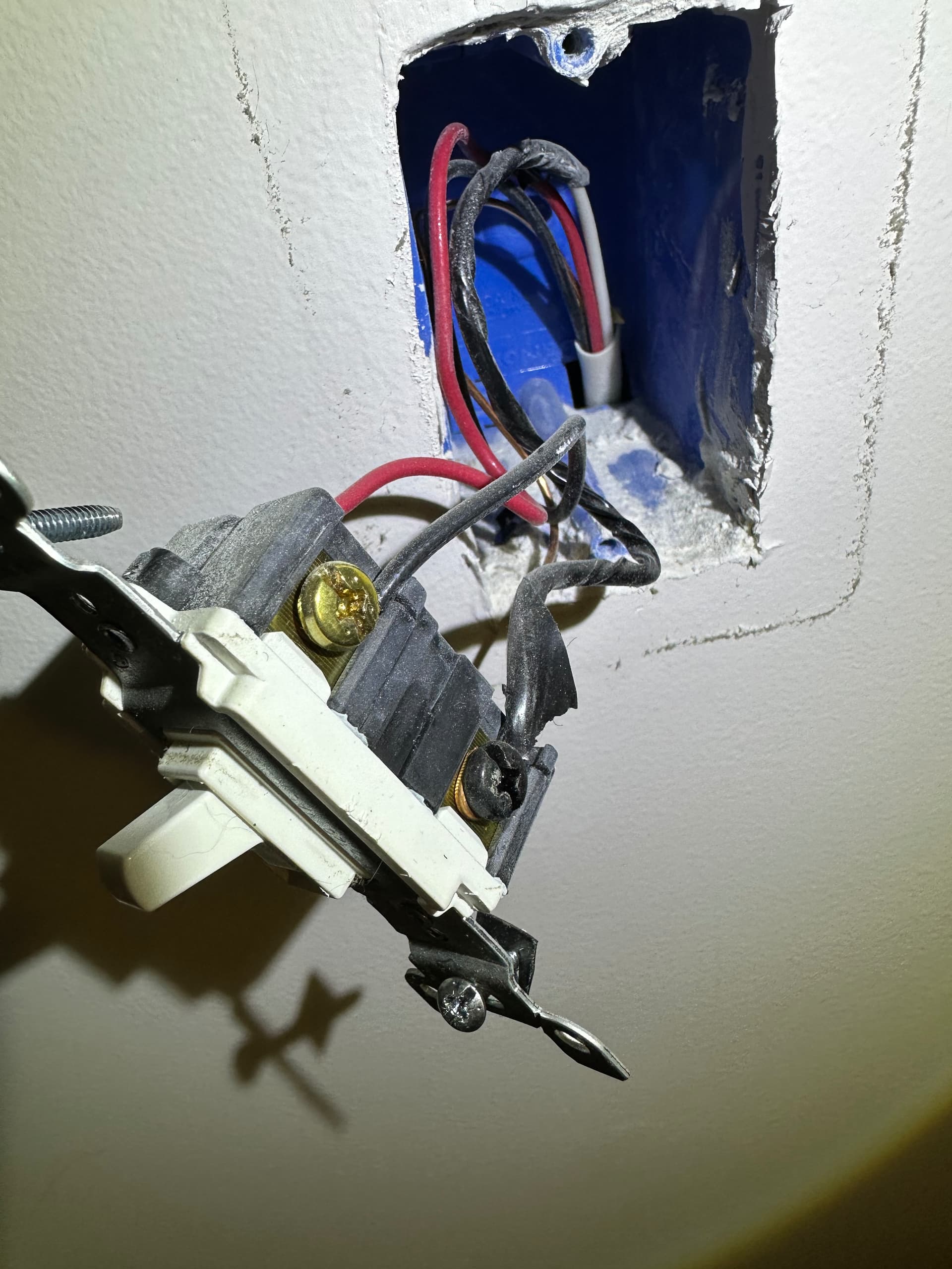
And then in this last photo he hooks up the taped wire to the last switch
Does anybody have any ideas how I can wire up 1 Zigbee dimmer and two aux switches? Or should I get an electrician to do this instead?