I am utterly lost. I am trying to find a wiring diagram that shows how to fit two blue-series dimmers into a three way circuit. I understand how to do the wiring on the end where where the line (“hot”) is sourced. I do NOT know what to do on the other end. I want dimming, and will settle for one handling the dimming and the other end just being on/off if needs be, but dimming from both ends would be nice. My hub is a C-8 (non pro) Habitat. Thanks very much.
Let’s get you going. When you have two dimmers in a three-way configuration, one of the dimmers will control the load and the other will simply be a scene controller.
The primary dimmer controlling the load is wired as a two-way. The other dimmer which is a scene controller is just wired with a hot and a neutral. It does not have a load and it is not wired to the other dimmer. So for that dimmer you just need to route a hot and a neutral to it so that it will power up.
Once you have the switches properly wired, you have two choices and how the scene controller interacts with the primary dimmer. If you just want the scene controller to send on/off messages to the primary dimmer, then you can do that with automations. However, if you want the scene controller to be able to dim and brighten as well, you will use binding to bind the two switches together.
Inovelli has wiring diagrams for how to do this. However, to figure out which one is appropriate I need to know what your wiring configuration is. Do you have a neutral configuration where there is a hot and neutral in one of the boxes? Or do you have one of the non-neutral variants?
If it is a neutral configuration, is it a line and load in the same box or line and load in different boxes?
The link below will take you to all of the wiring diagrams for the blue dimmer. But if you provide further details regarding your configuration we can figure out which is the right one for you.
1 Like
I will get with you either later today (6/24) or tomorrow; have some things that need taking care of here. In advance, thank you for your assistance and patience with an Inovelli “newbie”. I’m used to Lutron.
1 Like
A lot of what i wrote is moot. I have had my Inovelli stuff sitting so long I forgot what I bought! Turns out I bought an Add-On Switch for the other end. Here is what I found. The switch in the family room is in a 3-gang box. In it are fan control/light control combo, fed from a line (“hot”) in the box. Next is a switch for switched outlets; I am jumpering that connection to make the outlets “regular”, and to allow room for the two separate controls going in in place of the old combo.
Now to the one in question: the 3-way in this box has a black wire to the black common screw, and a red wire and a white. Note, however, that this black wire is NOT part of the line bundle in the box that feeds the other devices. So, my guess is that the line (hot) for the kitchen lights comes down from somewhere in the wiring to the kitchen lights.
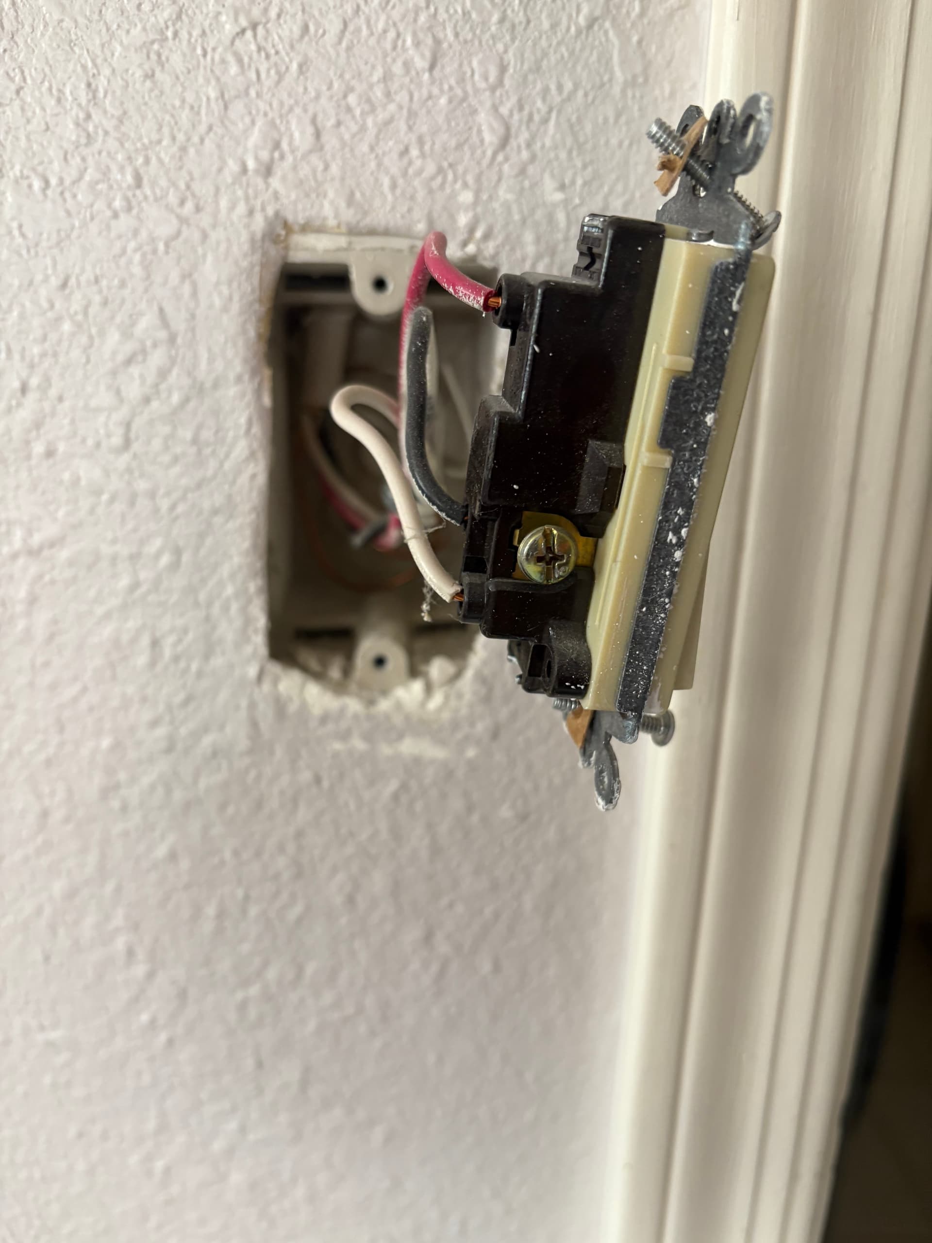
In the single-gang box, black wire to the black common screw, and the red and white wired in the same order as on the family room end.
Before I make something “go bang”, your guidance is welcome. I can handle the fan control and the one-way for the family room lights. I took pictures but am not sure how to add them as the image add image button puts in an “http:” thing when the photos I want to add are on my desktop. “”
Your thoughts? Thanks you!
Ok, so to make sure I understand correctly, one side of this 3-way is in a 3-gang box, and the other side is in a single gang box.
You would think that the line would be in the 3-gang box, but the black wire connected to the common screw is not a member of the bundled hots in that box.
As a first step, in the 3-gang box, remove the black conductor from the common screw and see if it is hot. Test with the switch in the single gang box in both positions, just to make sure.
To add pictures, instead of using the button, drag and drop them into the posting window.
There will be a bit of back and forth but we’ll see if we can keep from generating that pretty blue smoke . . .
Alll…righty. Had to go buy a meter as I can’t find mine.
To review: the black wire is on the common (black) screew at both ends.
I removed the switch on the three gang end entirely. Black is NOT HOT regardless how the switch is set on single-gang end.
With the single-gang box switch in one position, the white shows 121V.
If I throw that switch into its other position, white goes to 0V and RED goes to 121V.
Note, there is no neutral “passthrough” at the back of the single gang box; all that is there is ground and the three conductors.
As the mother with the screaming child said to the frustrated judge, the bawl is in your court! :-{)}}}
Ok, Thanks for the pics.
I can’t see into the 3-gang box. Can you trace the 3 conductors attached the switch in that 3-gang box. I believe that they all belong to the same 3-wire Romex, but you’ll have to confirm.
I have a good idea what this is, but I’ll wait for you to confirm a couple things. There is a tell in the 3-gang box, but I want to make sure of what I’m thinking.
If all three of those conductors attached to the switch in the 3-gang box belong to the same Romex, then do this please. Go the the single gang box and remove the black conductor from the switch. See if it’s hot. To be sure, test with the 3-gang box switch in both positions. If you have a non-contact tester, that’ll work. If you are going to test with a meter, you’ll have to test between that disconnected conductor and the ground, because there isn’t a neutral there.
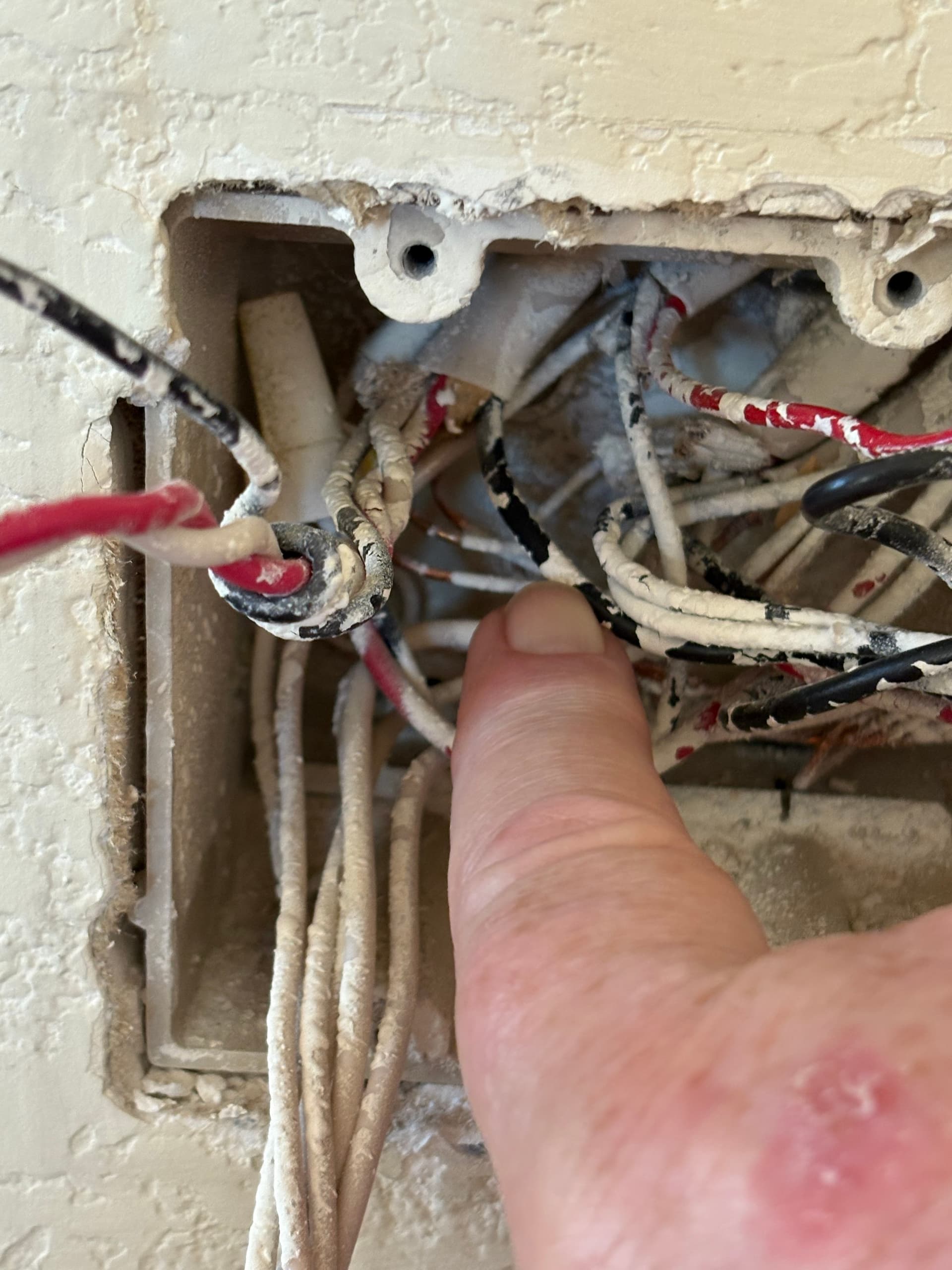
A-hah! I made a very close inspection. Note at the back that all three switch wires go into the same romex, but that there are more conductors! See my big paw, pointing a SECOND black wire coming back out of the romex and going to the bundle of blacks providing power to the other circuits in the box.
I went to the single gang box and did the following. 1) clipped the wire from the switch*. 2) with ground on one test lead and the black wire being touched with the other I get 121 volts.
Note: the switch has been completely removed from the three gang end so testing with the switch in both positions is not possible.
I think what we have is hot going all the way to the single gang box, where it is switched, or something. 3-way switching is - to me - second only to 1960s automotive electricals for confusion.
Is this enough to go by?
*May the great gods of the IBEW condemn to hell all electricians that use those insert holes in switches and outlets!
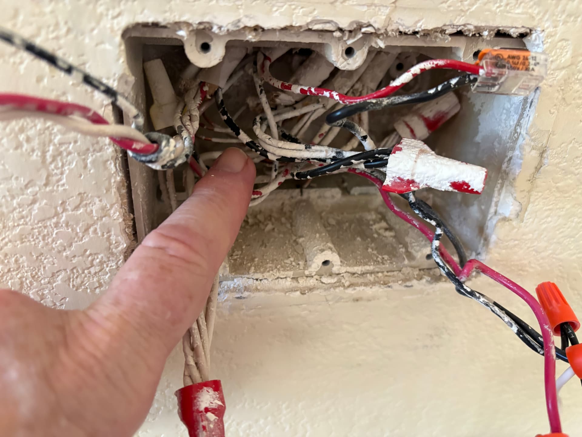
Ok, got it. So to confirm, the black from the 3-wire in the 3-gang box is attached to the black bundle to the right of your finger? And I’m gonna guess that black bundle is hot?
Shifting to the wires attached to the switch in the 3-gang box, note that the black is looped around the other two conductors. Some electricians use that to indicate the common or “switch leg” conductor, which in our terms means the Load (switched hot). Trace that black looped wire. It should belong to a 2-wire. The which from that 2-wire should be connected to a white, neutral bundle. I can’t see into that part of the box, so you’ll have to chase it. Thx.
1 Like
I will take a fresh look in the morning, after I cut power, and try to remove paint that is disguising so much. Painters who don’t stuff paper or something into j-boxes before spraying also deserve shipment to some sort of correctional facilty.
Please stand by til morning. Thanks again for your Job-like patience.
1 Like
Good morning, and, welcome to the continuing saga.
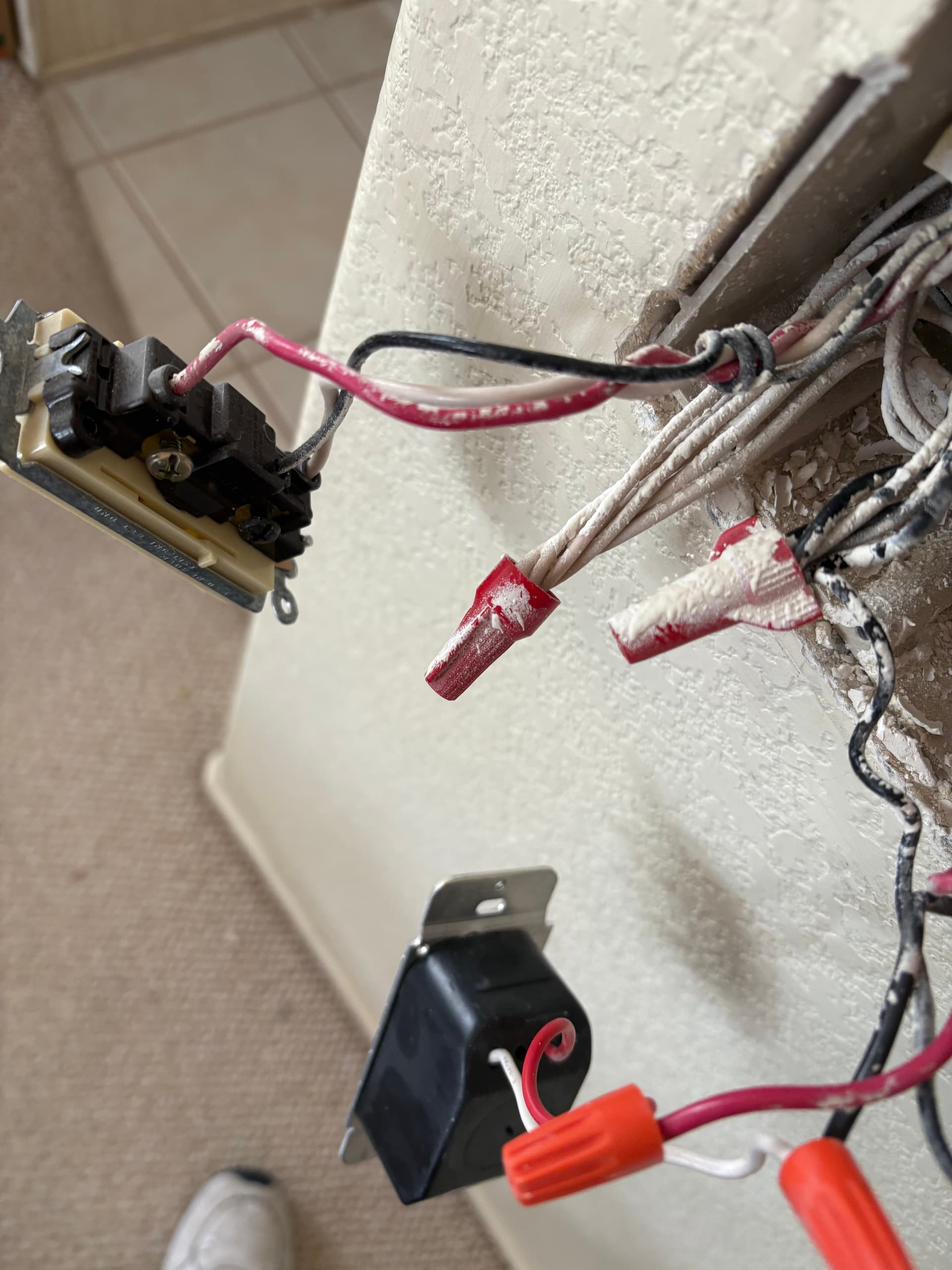
I pulled the power, and gently unwound that black wire to really dive into the back of the box. This is what I found:
-
That wrapped black wire leads back to a 2-conductor romex. You are right: it is paired with a white wire that goes into the neutral bundle.
-
The wires around which the black was wound goes into a 3-conductor. Red, white, and a black. The white had gone to a terminal on the switch I clipped out.
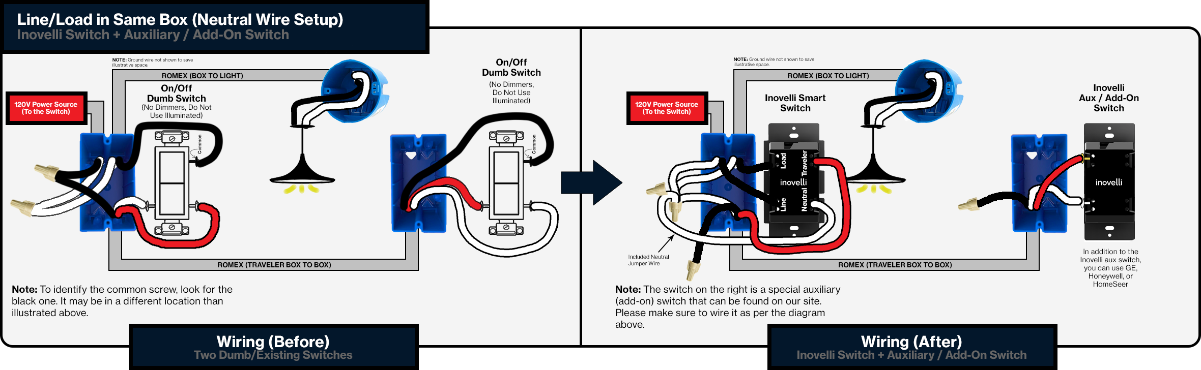
I think what I have is what is shown in this diagram. The way the various colors are shown - especially the routes the black leads are taking - leads me to this conclusion. If so, I believe I can take it from here but will await your comments and instri\ucttions. Thanks again!
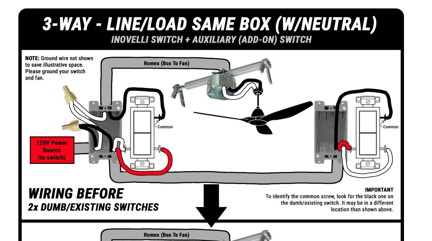
Yep, you have a Line and Load in the 3-gang box. The Inovelli wiring for an Aux switch is below.
The black of the 2-wire wrapped around the 3-wire is the Load.
You’ll note in the 3-gang box that the black from the 3-wire is connected to a hot bundle. That hot is sent to the other box, where it is connected to the common screw. It is then returned to the 3-gang box switch over one of the two travelers. That’s why you say alternating hots on the two travelers when you tested as you flipped the single gang switch.
Don’t forget to configure the switch as a 3-way w/Aux.
I’ll give it a try. Now, I have two new issues and am starting to regret using Inovelli.
I will open separate new entries, but, in summary:
-
I fitted a switch/dimmer to my breakfast room, along with a fan switch. The fan switch paired into my C-8 with no muss or fuss. The switch/dimmer will not, no matter what I do. This will be covered in detail in my separate entry.
-
Regarding the fan switch: I wenr into its setting, and have Type set as shown in picture. But! Go to preferences and there is nothing there for configuration to speak of, much less the “258 preferences” the on-line instructions mention.
Is there a part of the user forum where I can put my stuff up for sale? At this rate i think I want to go to something else.

@hydro311 can help you with the C-8.
All is solved! I used the help line at Inovelli and rather than the usual dumb stuff from AI (automated idiocy) I got answers that got my configuirations for the fan resolved, and brought my argumentative dimmer to life. It is working perfectly.
2 Likes