I’m trying to replace all the switches in my home with Inovelli Blue dimmers, as all my bulbs and fixtures are zigbee smart bulbs now.
For the circuit in consideration, I’m 95% sure it is:
Three-way
Line and load in different boxes
Neutral in the line box
No Neutral in the load box
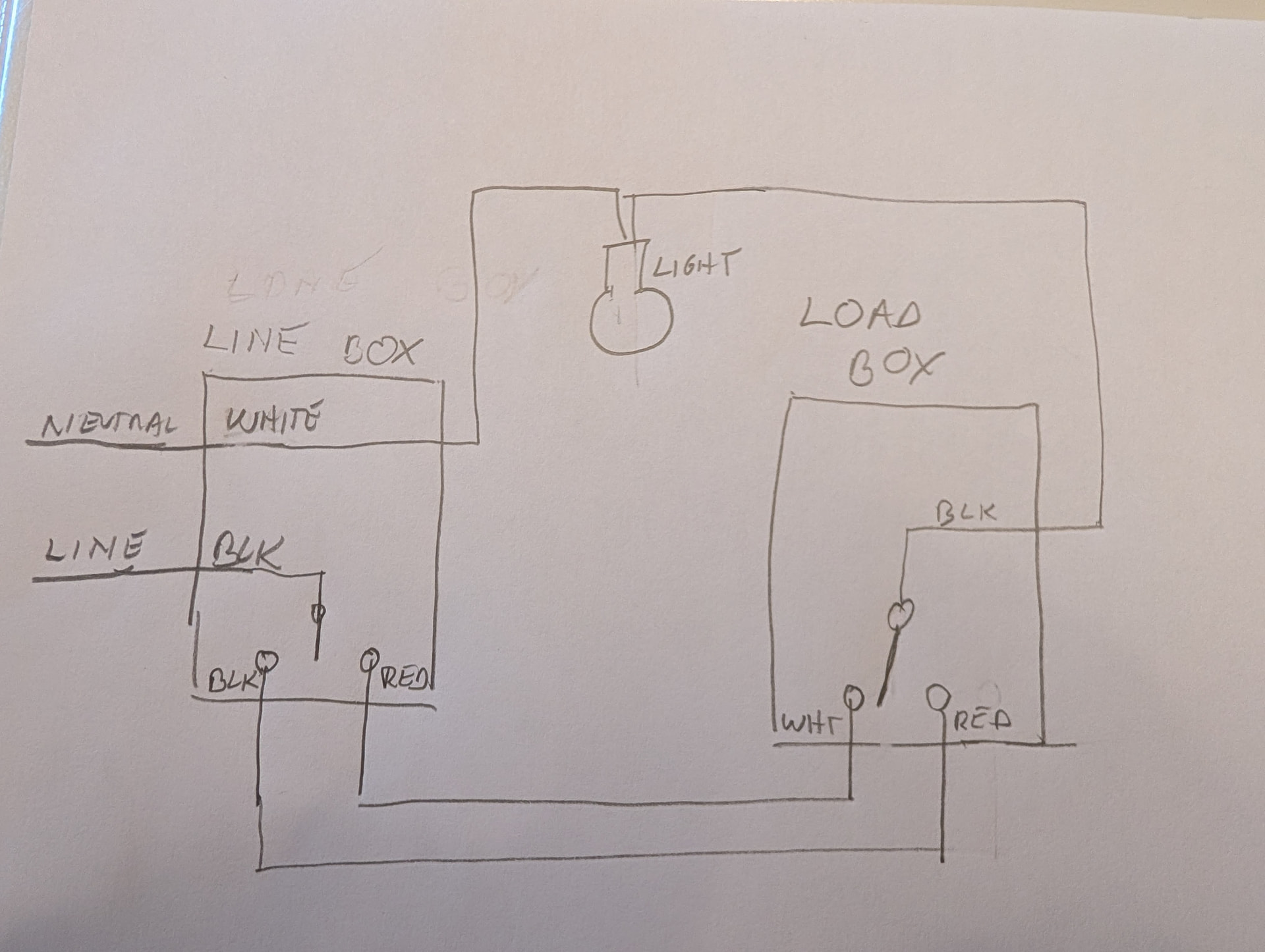
I’ve traced every wire with a continuity tester, and have the following schematic for the dumb switch circuit. The colors change on the travelers between the line box and the load box so there must be a hidden splice somewhere. Anyway it works
After install I run all my blue dimmer switches as remotes operating in smart bulb mode, so they really only need line and neutral. But I prefer to have them wired properly so I can use them as backup controls if HA and my zigbee network go down.
What are my options for this circuit? The relevant official wiring diagrams all show a neutral in the second box that is used for the blue dimmer. Thanks!
I wrote that draft a few hours ago. For the moment, I wired it so the two former travelers are now hot and neutral, the wire to the light fixture is always hot, and put the inovelli blue switches using pigtails so they have hot and neutral but no load. They are in smart bulb mode and just acting as remotes, which is fine for now. There’s just no way to use the switches as dumb switches if my zigbee network and HA go down, which I would prefer if possible.
It helps a lot more if you have photos of the wiring in each box.
So, with a multi-way circuit, it will typically be wired in 1 of 2 ways (there are other ways though).
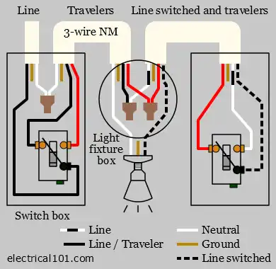
With the first of these methods, the neutral is passed through each box along with a set of travelers. The Line will enter the circuit on one side, and the Load will leave from the other side of the circuit.
For this method, if using an Aux switch, you can put the main switch in any of the boxes, and you would repurpose the travelers as a Traveler and either a Line or Load. When moving the main switch later in the circuit, you would instead pass the Line down one of the travelers until it gets to your switch, and from there you would send Load over the other traveler. If utilizing existing “dumb” switches, you need to put it in the first box where the Line comes in.
With the second of these methods, Line and Load come into the same box, and the 3 wire cable going to the other switches contains a “common” wire along with two travelers. Even though there may be a white wire in this group, it will not be a neutral. This is commonly referred to a “dead-end” 3-way and you usually only have the 3 wires from this cable entering the last box and the power has to “turn around” and go back to the first box.
For this method, the main switch has to be installed in the first box containing the Line and Load. If using an Aux switch, you repurpose the other wires as a Traveler and a Neutral, capping off and abandoning the 3rd wire in the cable.
EDIT:
Taking a closer look at the diagram you drew, I noticed that the travelers change color between the switches, which likely means that the light is wired up in between your switch boxes…
Yes - all of my circuits are the second type, with no neutral running to the second box, just a pair of travelers. In the end I had four circuits like this. In one of them, the color changed between the first and second box, but when I traced all the circuits manually with a continuity meter, the light was not actually in the middle, like your diagram. it was definitely wired as –line-switch=switch-fixture-neutral- (with the equals sign representing the two travelers going between switch one and switch two).
In any case, I came to the same conclusion as what you recommend for that situation: for all four of these circuits I repurposed the two travelers as line and neutral, and the switches are all set in smart bulb mode.