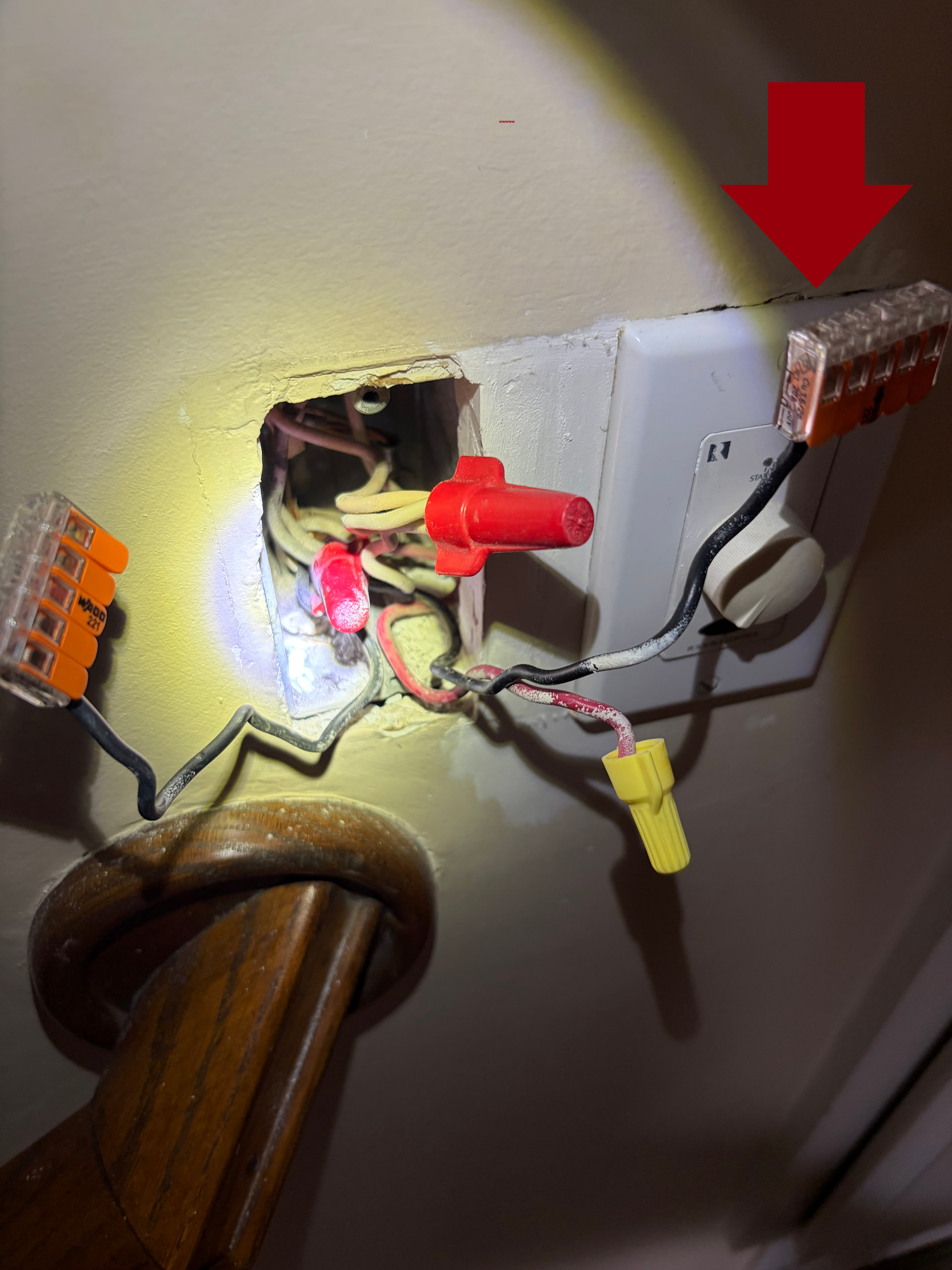
I’m trying to setup a 3-way with two Blue mmwave dimmers. I believe the wiring is setup in a switch loop. Please let me know how I should wire this to have both switches working in a 3-way. The light fixture is in the middle of the two switches. After separating the wires and testing, it looks like Switch 1 (see picture below) only has power coming in - the Light Fixture and Switch 2 (see links below) do not have a standalone hot wire. I’m so lost - please help.
Ok, it looks like power comes into Switch One, and sends two travelers and a neutral up to the light. After the travelers get to Switch Two, it sends the Load back up to the light to be used with the neutral from Switch One.
Are you looking to use 2 stand alone Dimmers, an Aux Switch, or a Dumb Switch in the Switch Two location?
Nah, if there are only 2 cables, it should be fairly simple… you should have a 2 wire cable, black and white, and a 3 wire cable, black, red, and white.
EDIT: Taking a closer look, it definitely appears that there are more than only 2 cables in the Switch One box, but ultimately it shouldn’t matter… The basics still apply with it sending a neutral and two travelers up to the Light box, the travelers are sent down to Switch Two, and the Load comes back up to the Light box to make the light work.
You will want to do the following… Based on the existing wiring in the light box, we will use the red to carry power over to Switch Two…
So, at Switch One, you will connect the red wire to your Line black wire… both into the switch will be fine… The other black wire will be your Load wire. This will let you carry both Line and Load up to the Light box. And obviously you will need to connect a Neutral to your dimmer as well, using the included pigtail to the bundle of neutrals.
At the Light box, you will connect both of the white wires together as this will allow you to send Neutral down to Switch Two. The black wire from Switch One will power your light, and the other black wire will be abandoned and remain unused.
At Switch Two, you will connect the red wire to Line and the white wire to Neutral to power your “remote” presence sensor. You will leave black unconnected and cap it off.
You will then need to “bind” the switches to each other and set the mmwave control options on both switches to “Disabled” to allow Home Assistant (or whatever) to use the occupancy detection from both switches to control if the lights get turned on or off.
I will try this - thank you so much! Regarding the white wires at the light. If I connect both white wires together to to give neutral to Switch 2, how/should I connect a white wire to the light fixture (it needs a black and white wire), another pigtail and jumper to the light switch?
You will just put both white wires into the same wago and either add a pigtail for the fixture, or put the fixture wire directly into the 3rd spot in the wago.
No dice unfortunately. There is power going into Switch 1, but it’s not lighting up. Also, I checked the red wire at Switch 2 (connected to Line on the switch) and there is no power coming in.
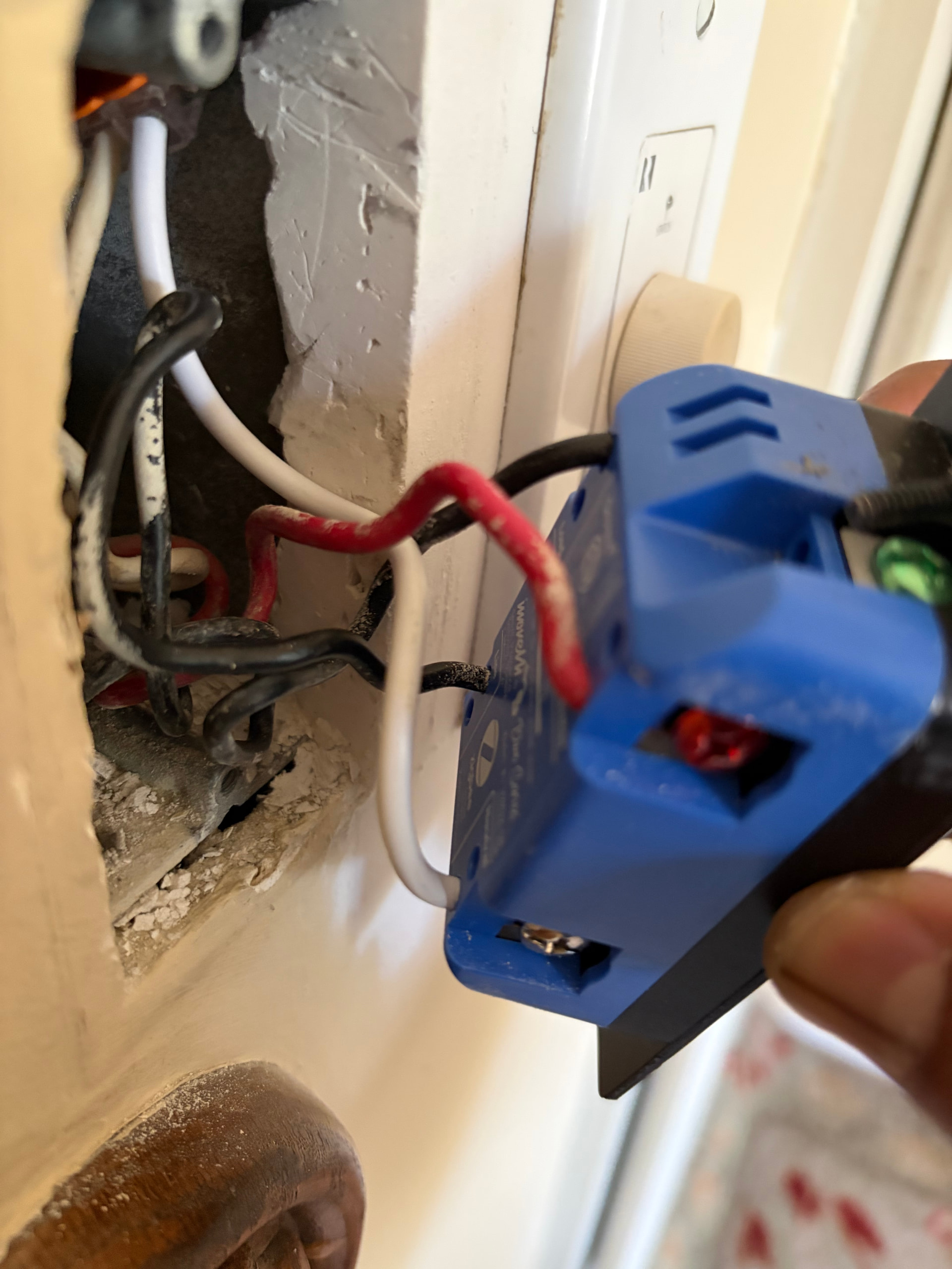
When you said “you will connect the red wire to your Line black wire… both into the switch will be fine,” did you mean that I should just plug the Traveler (Red) and Line (Hot Black) into the switch directly? That’s what I did - see picture below of Switch 1.
Okay, I’m dumb. I figured out that you meant that both the traveler and line should go under the same screw in the Switch 1. I did that and there is now power flowing to Switch 2 through the traveler. However, both switches are not lighting up/turning on. Is it possible that I killed them at some point during my attempts or could it be something else?
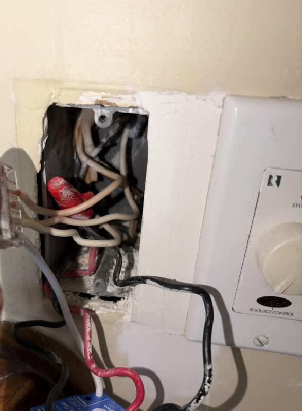
Here is a better picture of the wiring inside Switch 1. You are correct that there are more than two cables - it looks like 3. One coming in from the top right, another from the top left, and the third from the bottom left.
Do you have a multimeter? or are you using a non contact tester?
If you have a multimeter, verify 120v between the hot wire and the neutral… because if both the hot black and the red are showing as hot, there may be an issue with the neutrals not being connected properly.
Non contact tester. I took out one switch and put it into a basic single pole setup and it didn’t work. I’ll restest your method once I get new switches - thanks again.
If you have the light installed, just put both blacks together to see if the light powers on… if so, then at least one of the switches should be powering on.