It’s hard to verify the wiring of the light bulbs, but at my main switch outlet I have white/black for line, and red/white/black for load.
I’ve tried to wire it like the instructions in the manual state with my original “dumb” switch, but I loose 3-way functionality. Whenever I turn the dumb switch to “off”, I’m not able to turn the light on from my Inovelli.
(see 1st reply)
I thought this might be the case based on instructions in the manual, so I tried a GE add-on switch. In this configuration (based on the manual), neither switch works.
(see 2nd reply)
Is this expected behavior with a dumb switch? Is there any way I can make both switches work in a 3-way configuration?
I didn’t originally, but did after your message. With it set to “dumb switch” mode, I can now hear the relay click when I press the switch, but it didn’t change the 3 way behavior with the dumb switch. I haven’t tested with the add-on switch.
It’s going to have to be set to 3-way momentary and you are going to have to use an aux switch. You can’t use a dumb switch with a no-neutral configuration.
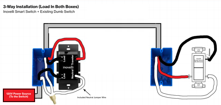
Your initial post states the power comes from the light and there is no neutral wire at either switch. Yet the 2 diagrams you are attempting to follow are both for neutral wiring.
As mentioned above, with no neutral you’ll need the AUX switch (will not work with a dumb switch) and you’ll need to use the diagram for 3 way wiring with no neutral.
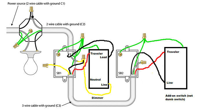
If your original drawing is correct, you have power going to the light first. @MRobi’s drawing is correct but it may confuse you because it reflects power going to the switch. This drawing is the same as above but it may make more sense to you:
OK, did you figure this out or are you still having problems?
If you are still fighting it, I have a question. You say you have a Black/White and a Black/Red/White cable in the “main” switch. Was this circuit already a dumb three way (two different switches) circuit? If so, what wires do you have in the SECOND switch box? Obviously you have the Black/Red/White, but are there any others? Another Black/White for instance?
Secondly, do either of the switches share a box with another switch?
My initial diagram exactly describes what was originally in each box. No extra wires other than the bare copper ground wire. It was originally a dumb 3-way switch.
I have it hooked up the way suggested in @Bry’s diagram and set the approriate settings for non-neutral and aux switch
The suggested configuration mostly works. The Inovelli side seems to work about 95% of the time, or at least often enough to make me wonder if I just hit the wrong button in the dark when it doesn’t. The Aux switch only seems to work 70% of the time, at least when I’m quickly (within a second) turning the lights off/on and then back on/off. I’m not sure if this was related to the load (I do have all LED’s on the circuit, but I have enough of them that I’d expect it to be over 25W.
I’m waiting on a bypass switch to be delivered from Amazon just in case. The lights definitely flicker when dimmed low enough.