Hello! Long story short, I’m annoyed that I found out that one of my switch work box has supply but for a different circuit into a different room (GFCI powder room outlet) so I couldn’t splice it since will trip the GFCI and is not code compliant. So i had to be more creative found a solution! So this involves a pair of 3 way switches, and I wanted to place a pair Inovelli white switches in load & traveler only switch box, since this will be the area that is most convenient and aesthetically pleasing. I just want to make sure everything is correct and is code compliant in US standards. (see pic below)
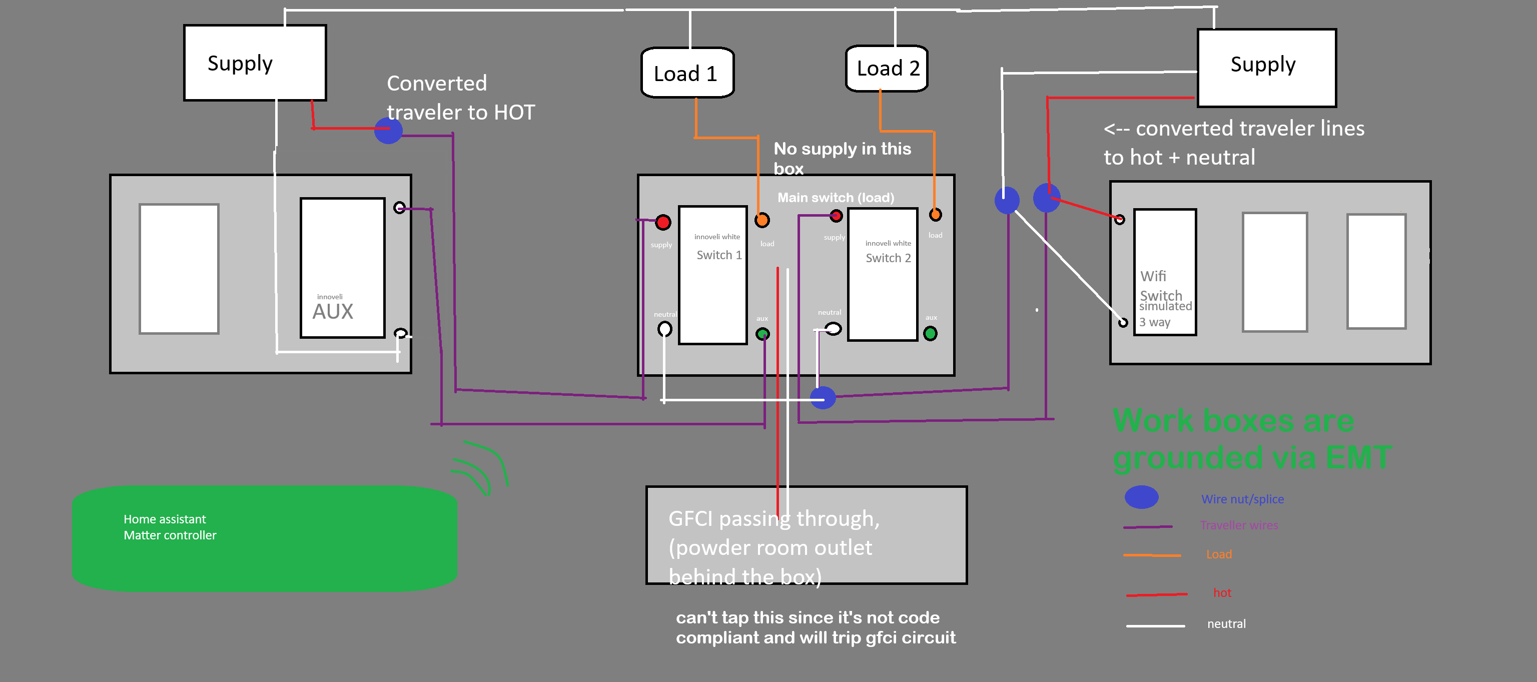
Ok, in the attempt to understand what you have (as I dislike the use of a hand drawn diagram instead of just supplying photos of the wiring…) I am going to restate some of what you are trying to show in your diagram.
From left to right, box 1 with 2 switches, box 2 with 2 switches, and box 3 with 3 switches.
Load 1:
Power enters box 1 and you have a 3 wire cable going to box 2 for a dead end 3-way. You want to utilize one Inovelli switch and one aux switch.
Load 2:
Power enters box 3 and you have a 3 wire cable going to box 2 for a dead end 3-way. You have a wifi switch in box 3 with no load attached to work along side an Inovelli switch in box 2.
Box 2 only has the two 3 wire cables intended for two dead end 3-way switches.
Does this accurately describe the situation?
If yes, and you want the Inovelli switch for Load 1 in box 2, your best bet is to connect it as a no neutral connection, leaving you with an option of only the Dimmer switches eliminating the possibility of using the On/Off switch for that circuit (can’t connect the On/Off switch in a no neutral wiring configuration). You could move the Inovelli switch to box 1 and use the Aux switch in box 2 while utilizing the neutral without an issue, but I assume you want both switches with LED bars in the same box.
For Load 2, you are capable of repurposing the 3-wire cable as a Line/Load/Neutral, so there is no issue there.
The issue I see with the above diagram is using the neutral sourced from box 3 for Load 1 sourced in box 1, even if they are the same circuit.
Yes that is accurate and thanks for the time understanding this. All those wires are inside the work box but just drawn externally since my mspaint skills are lacking. Also why is neutral sharing an issue? I also think I might revise this a bit, I might just replace the box 3 wifi switch with another inovelli aux switch (since i already have it) and use that converted HOT traveler into an aux signal. So in short box 1 supplies hot and box 3 supplies neutral–using the spare traveler wire.
NEC 300.3(B)
(B) Conductors of the Same Circuit. All conductors of the same circuit and, where used, the grounded conductor (the neutral) and all equipment grounding conductors and bonding conductors shall be contained within the same raceway, conduit body, auxiliary gutter, cable tray, cable bus assembly, trench, cable, or cord unless otherwise permitted in accordance with 300.3(B) (1) through (B) (4).
Basically, for Load 1, as the supply comes from box 1, that neutral should travel with the wires going to box 2 if it is going to be utilized. The same for Load 2 in box 3. For Load 2, you are indeed including it with the live wire going to box 2, but only for the wires in the same cable. For a device, you don’t want the live and neutral wires to come from different cables.
I am not saying it won’t work, I am saying that isn’t how it should be done.
Luckily, if you are intending to use a Dimmer for Load 1, you can connect it without using a neutral, allowing you to pass Line, Load, and Traveler over the 3 wire cable. This still allows you to move the dimmer to box 2.
I looked into the neutral sharing issue and understanding how AC works is fascinating. So I guess i will disregard my plan and just do it this way: Box 1 and 3 will have AUX switches, box 2 will have 2 smart switches. I wire aux with hot in the neutral port, also send that through traveler, and wire signal to the other traveler. (repeat it in box 3), and I would just normally wire the 2 smart switches in box 2 but without neutral. That seem correct?
Yup, if you want to use Aux for both loads and have the Dimmers in box 2, then both of the 3 wire cables will carry Line, Load, and Traveler.
Your Aux switches will be wired to Line and Traveler, Line in place of the Neutral, and the Dimmers will be wired with Line, Load and Traveler
EDIT: One thing to keep in mind though when wiring them up without a neutral is that you may need to use a bypass if there isn’t enough of a load on the circuit. I think the number I normally see is 25w or so, so if you only have a single low wattage LED bulb, that may not let enough current pass through to power the switch.
The good thing though is that you could wire them up in the switch box provided there is enough room, as normally they’d have to be installed in the light box. These are wired in parallel with the light between the Load and Neutral, and since you DO have a neutral for these circuits (in box 1 and box 3) you could wire the bypasses directly in the switch box.
Oh that is interesting i can tuck that bypass in the switch box. So if im understanding correctly, i place it on box 3 (it has the normal LED bulb 3 way switch, which is load 2 in the diagram), hook one leg into neutral and the other in hot? Box 3 is perfect too since it has room in there!
To be clear, while yes you connect it to the “hot”, you don’t connect it to the Line, you instead connect it to the Load going to the light… as if it were another light fixture.
You might need one for Load 1 as well, depending on what it is powering.
Oh gotcha, the loads are only in box 2, and which it doesn’t have any neutral (that supply in the diagram is only passing through the box and is not terminated). The bypass would just need to go in the light fixture i guess. Anyways thanks for you help!
What do you mean the loads are only in box 2? If box 2 only contains the two 3 wire cables, one from box 1 and one from box 3, then the load should travel back to box 1 and box 3 respectively before going back to the lights the switches control.
Box 2 only has 6 wires, 2 sets of 2 travelers (2 purple and 2 gray color), and 2 sets of load (orange and yellow color) that goes to the light fixture.
Are you perhaps in Chicago? or in a highrise apartment/condo building?
As it sounds like you have wiring run in conduit… which is an important fact that would have been obvious with photos but not a hand drawn diagram… one of the many reasons I dislike them in lieu of actual photos.
All my above recommendations are predicated on the assumption of romex wiring. I can’t guarantee anything that I have suggested will be applicable to your situation, as it is vastly different than what was assumed. Instead of a 3 wire cable between boxes, it is likely that the wiring doesn’t even go directly between boxes, but either to the light box or another intermediate junction box.
EDIT: Well, I guess you should still be able to pass Line and Traveler over the exiting traveler pair… as even if they go to another box somewhere, they should still be direct connections… so that advice should still be applicable, but that does mean than any bypasses that need to be installed will need to be installed at the light.
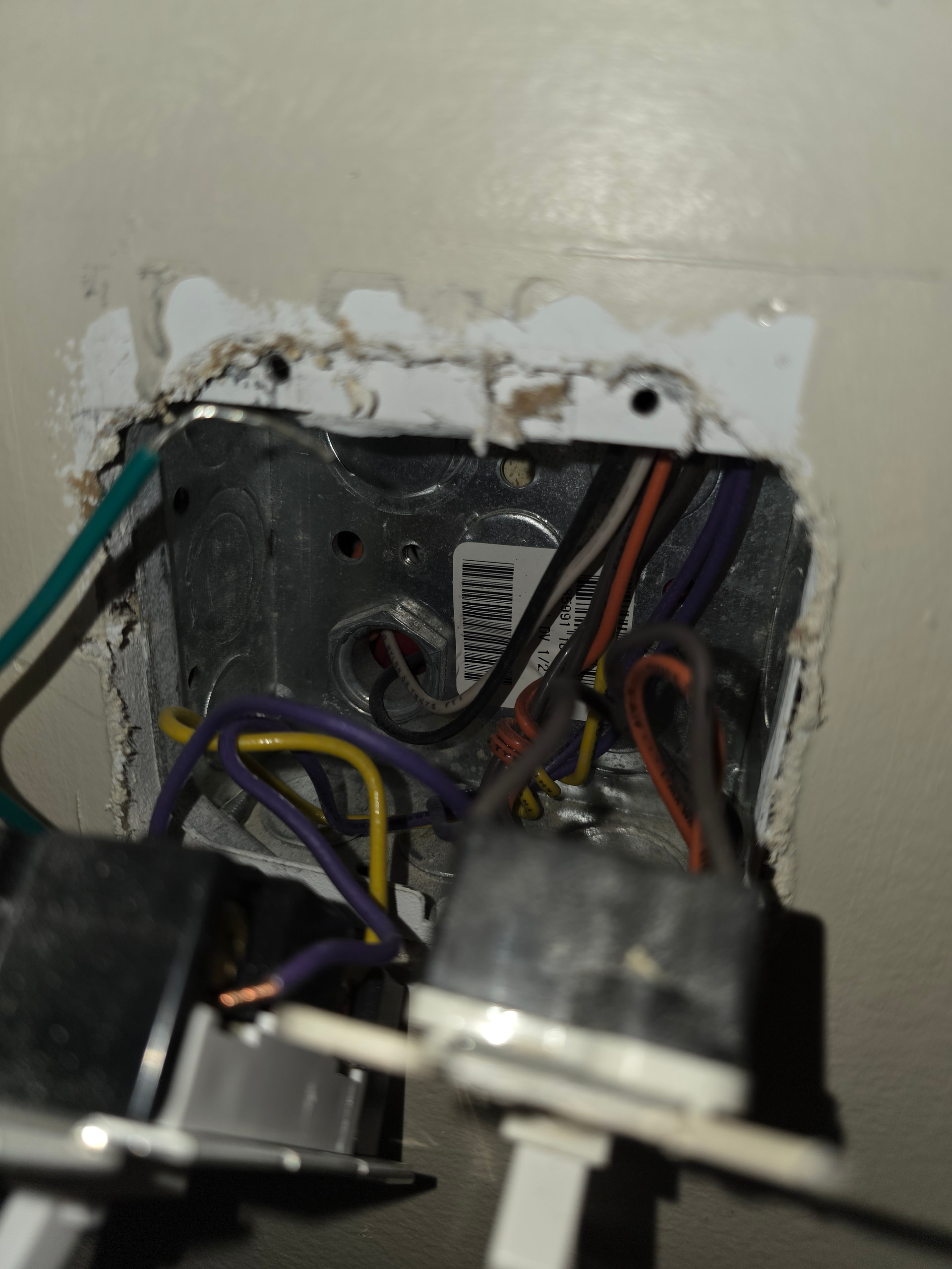
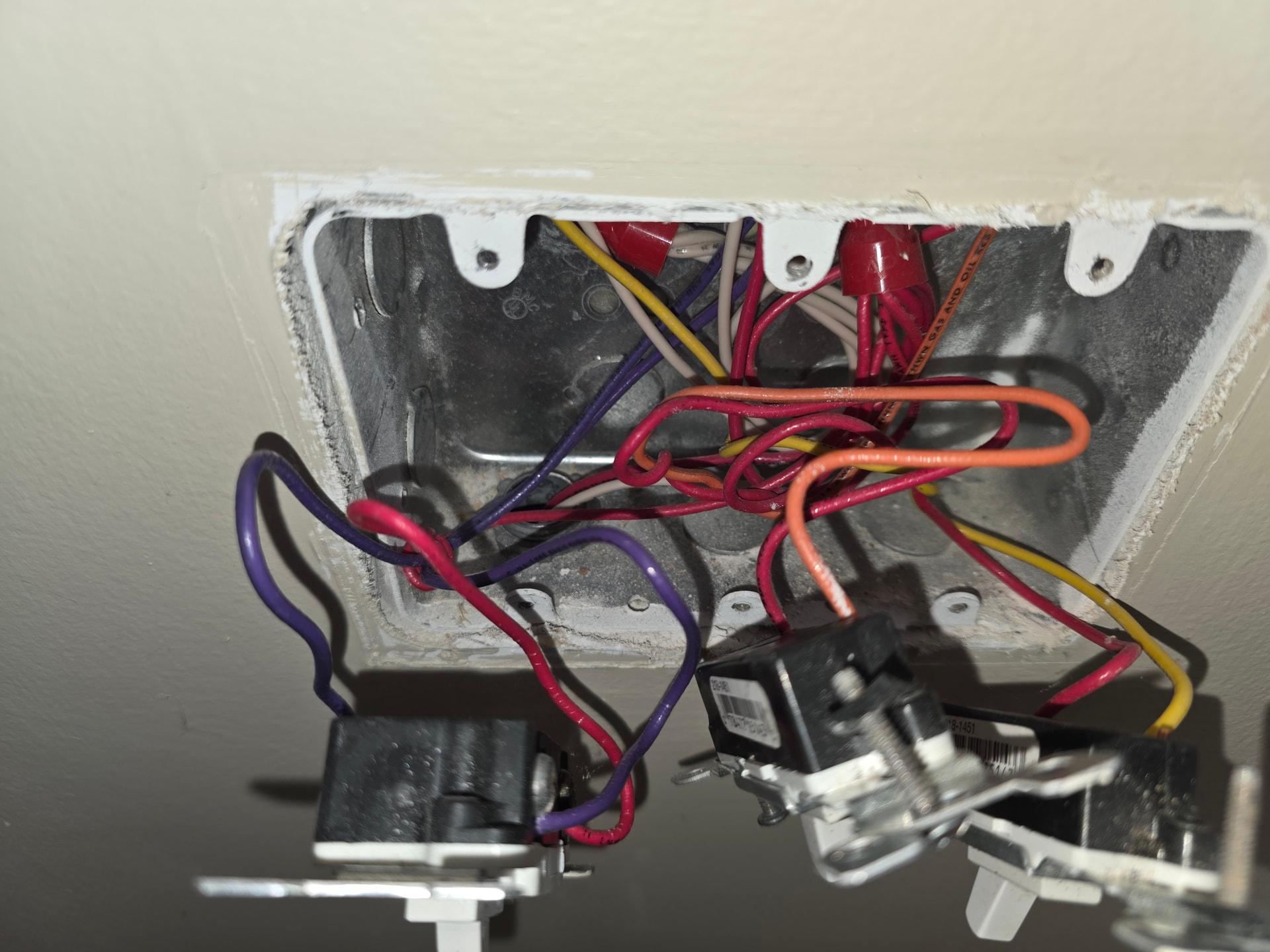
Lol, yup, and given the context of the photos, there is nothing wrong with the diagram, it is just that the diagram on its own doesn’t provide the whole picture, so to speak 
Anyway, as added to my previous post, there shouldn’t be too much of a problem repurposing the travelers, and would be basically impossible having the aux switches placed in box 2 (unlike if it were wired using romex, as then it would have been my preferred setup)
Hey no worries! I really appreciate for your time and help! I probably will just limit my dim threshold so I won’t need a bypass cap to prevent any flicker. There was a originally a “dumb” dimmer on box 2 (left side of the picture with the ground leg) and my light fixtures weren’t flickering at all so I’m optimistic!
As a clarification, it isn’t about the dimming level, but when the dimmer is connected without a neutral, it leeches the power through the load wire… basically using the load wire as a neutral. It isn’t only to prevent flicker, though it might help.
If the connected load isn’t large enough, it may not be able to grab enough power to power the switch. “Non smart” dimmers aren’t electronic, so don’t need a neutral, and control the output level through resistors (really old school) or through a TRIAC to modify the sine wave going to the load. These don’t care what is attached and will work regardless of the load… now, how the load reacts to the dimmer is another thing altogether.
If you can try without installing a bypass, then do that first… you may not need it. The whole subject of using a bypass was just added as extra information in case you needed it because of not using the neutral connection on the switch.
EDIT: Minor rewording.