Hi Everyone - Brand new here and need some assistance wiring a red series dimmer in a 3 way / no neutral set up with aux switch. None of the wiring diagrams depict my current set up.
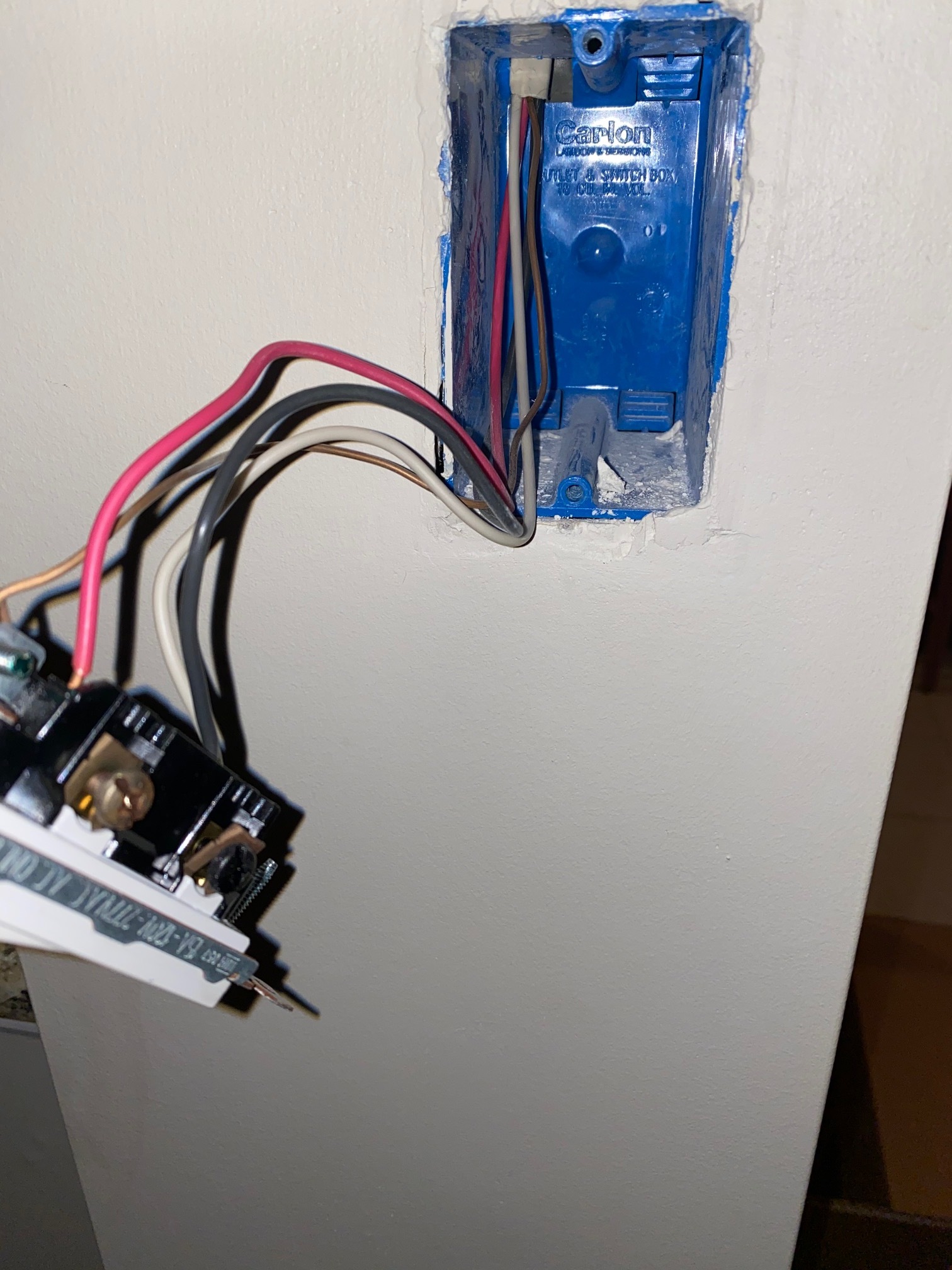
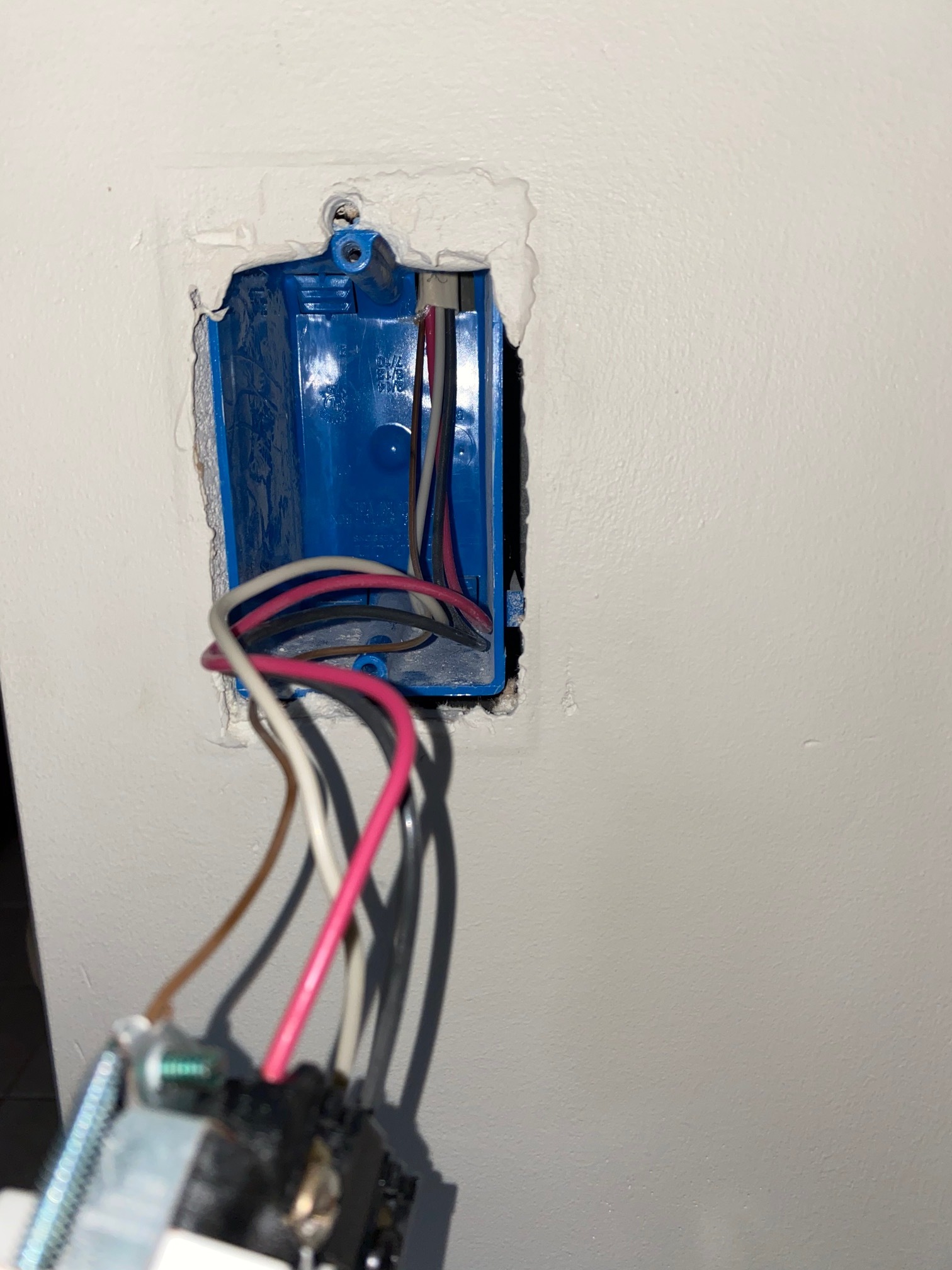
I have two switch boxes that appear to have identical wiring - they both only have one 4 wire romex coming into the box and the switches are wired identical (see pics below). As an FYI, these switches control a set of nine recessed lights currently.
I did take apart the wires in each and tested the voltage and got the following results:
Switch box 1:
Black wire always had 120 v and the others zero no mater the position of switch 2.
Switch box 2 (with switch 1 in the “off” position):
White 120v rest zero
Switch box 2 (with switch 1 in the “on” position):
Red 120v rest zero
Any thoughts in which switch box the inovelli switch gets wired and which wires go to which terminal? Similarly which box do I install the GE add on switch and to which terminals are the wires connected?
Any assistance would be greatly appreciated.
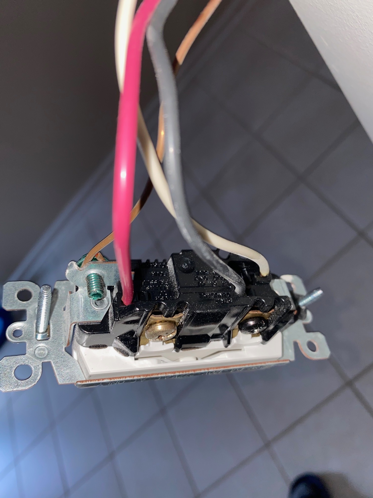
First two pics are of switch box 1 and second two pics are of switch box 2.
Thank you @harjms for your feedback and assistance. I was a bit confused myself at first as you would think to expect a two wire romex. Having said that, the “black” wire in switch box 1 seems to have a constant 120V no matter what position the other switch is in. Maybe @Bry can solve the puzzle…
@jmstravelllc - So I would be confident that the dimmer would go in the box 1 (where constant hot is). That would be line and the RED/WHT would be the travelers. I assume then it goes back to the light to cross connect down to the other box 2. In box 2, the BLK is the Common back up to the light. Just need to figure out how to connect the AUX…
@harjms that is helpful. So, if I am understanding correctly, in the first box dimmer with black wire (constant hot) into line terminal. Does it matter which wire goes into load/traveler or are the red and white interchangeable on the dimmer switch? In the AUX switch, would I cap the “black” wire and then just have to figure out which terminal the white and red and connected?
That’s where I’m stuck at…in the AUX non-neutral scenarios I’ve seen, the Line/Load are in the same box…so you feed the hot to the neutral port, and traveler to the traveler port from the Inovelli. The Load is cycled from the Inovelli…but your wiring can’t support (at least from what I can see); you may have to re-wire at the light box to send constant hot to box 2 where the load wire is…then use the aux in Box 1…
Ok. Appreciate your assistance. Not sure how easy it will be to wire from the lights - its a set of nine recessed lights. If it requires re-wiring, I will just skip it. Odd as this set up was just wired a few years back and wired totally differently than all my other switches. I have installed over 20 throughout the house with ease and stuck on this one for now.
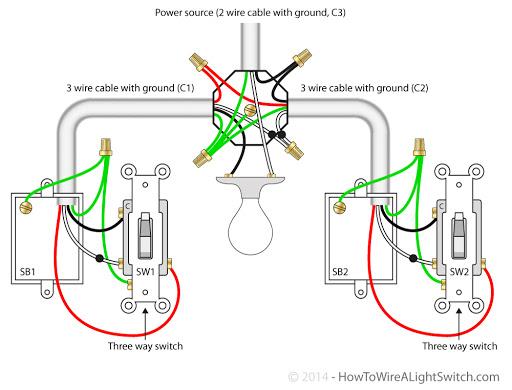
I read this quickly. It looks like you have one 3-wire going to each switch box. Is that correct? (Don’t count the bare ground in the wire count.)
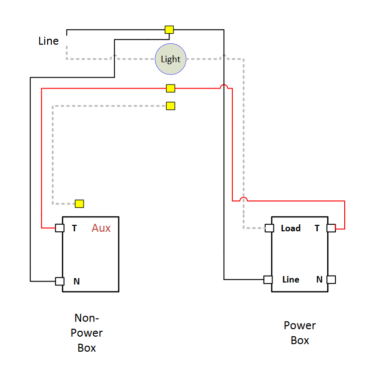
What that means is that you have power to the light with the light in the middle with a 3-wire going from the light to each of the two boxes. So you basically have a non-neutral on both sides. It looks like this:
Is this what you have? It’s doable as a non-neutral, but you’ll have to be able to get to the light to do some re-wiring there.
Thank you for reaching out. I am not sure what I have at the light as there are a set of nine recessed lights in the set up, but yes I just have a 3-wire romex to each switch. Maybe the voltage readings will help…
Switch box 1:
Black wire constant 120 v and the others zero no mater the position of switch 2.
Switch box 2 (with switch 1 in the “off” position):
White 120v rest zero
Switch box 2 (with switch 1 in the “on” position):
Red 120v rest zero
Thanks. AFAIK, there is only one possible wiring schema with what you’ve described. The voltage readings don’t help make it any easier. Since you have to get to the first light to re-wire, you can put the Inovelli in either position, wiring accordingly. If you can’t get to the first light, then you’re dead in the water.
Sorry that it’s wired that way. If the work was done a few years ago, it should have been considered new work and complied with the code that requires a neutral in the first switch box. But that’s not what you have, unfortunately.
I appreciate the feedback, and no need to be sorry. I have been reading through a lot of posts and most mention you need to find the “constant” hot so that is why I thought providing the voltage readings might assist. Maybe someone else that has a similar set up will come across and have some thoughts…being that I am new, feel free to tag others that you might think could be of assistance.
Yes, ordinarily you do need to find the constant hot, as that would be where you would put the Inovelli. The idea is that you would place the dimmer there as a non-neutral and then use an Aux in the other position. In your wiring scheme, however, you have to re-wire at the light to get the appropriate connections to the Aux. So in your case finding the hot doesn’t matter so much.
@Bry thank you for this. On another note, I do not know how to link to another thread, but found one that might be similar.
Do you think its worth a shot?
No neutrals in either box
Line/load in separate boxes (Line in - Box 1, Load - Box 2)
2 traveler wires running between the boxes
Solution I wanted to share (and also get everyone’s thoughts on):
In Box 1, I installed a GE aux switch:
The line (power) and traveler wire A are connected to “neutral” (which allows the power to travel consistently along traveler wire A to Box 2).
Traveler wire B is connected to “traveler”
In Box 2, I installed an Inovelli Red w/ scene (LZW31-SN):
Traveler wire A is connected to “line”
Traveler wire B is connected to “traveler”
Load is connected to load
Inovelli has been configured (at the switch) to non-neutral, 3-way aux
This solution worked for me and I am hoping it will help someone else (as I spent about 2 days trying to figure this out). The GE switch in Box 1 works fine, although it can take a couple of seconds to respond. I am going to try and reduce the on/off ramp time on the Inovelli to see if that speeds up the response time from the GE switch.
Thanks @harjms - I am indifferent as to where the Inovelli is installed.
So I would install the Aux in “box 1” and Inovelli in “box 2”. IBased on my wiring, do you have an idea how to interpret? I know the black wire in box 1 is the power, but what is traveler a and b? And in box two what would be the load? Presumably traveler a and b would have to match box 1?
Switch box 1:
Black wire always had 120 v and the others zero no mater the position of switch 2.
Switch box 2 (with switch 1 in the “off” position):
White 120v rest zero
Switch box 2 (with switch 1 in the “on” position):
Red 120v rest zero
So in box 1, connect BLK wire to neutral port of Aux switch. Also connect the Red wire to the second hole of the neutral port on aux switch. Connect remaining wht wire to the traveler port.
In box 2, connect the Red wire to the Line port of Inovelli. Connect the BLK wire to the Load port, and wht wire to the Traveler port.
Secure the connections tightly. Also be sure to connect the bare wire to the Grounds on both switches.
Configure the switch for Nonneutral and 3 way momentary via config button or include to the hub and set via parameters.
@Bry - I’m really hoping it’s tied RED-RED, WHT-WHT between the two sets of ROMEX…hopefully. Definitely worth metering or taking a look at the light box.