The title could have also been: Those who like puzzles, please lend me your help!
So I’m struggling to wrap my head around how I should be installing the Blue 2-1 and Aux Whites into two 3-way setups in one of my rooms - and I really don’t want to screw it up.
To set the stage:
Switches 1 and 2 control a set of ceiling lights
Switches 3 and 4 control a (different) set of ceiling lights
Switch 1 is currently a dumb switch, and I want to replace it with a Blue 2-1
Switch 2 is currently a dumb switch, and I want to replace it with an Aux white
Switch 3 is currently a dumb switch, and I want to replace it with an Aux white
Switch 4 is currently a Red Series Dimmer (from a prior install, that I can’t guarantee I did 100% correctly ), and I want to replace it with a Blue 2-1
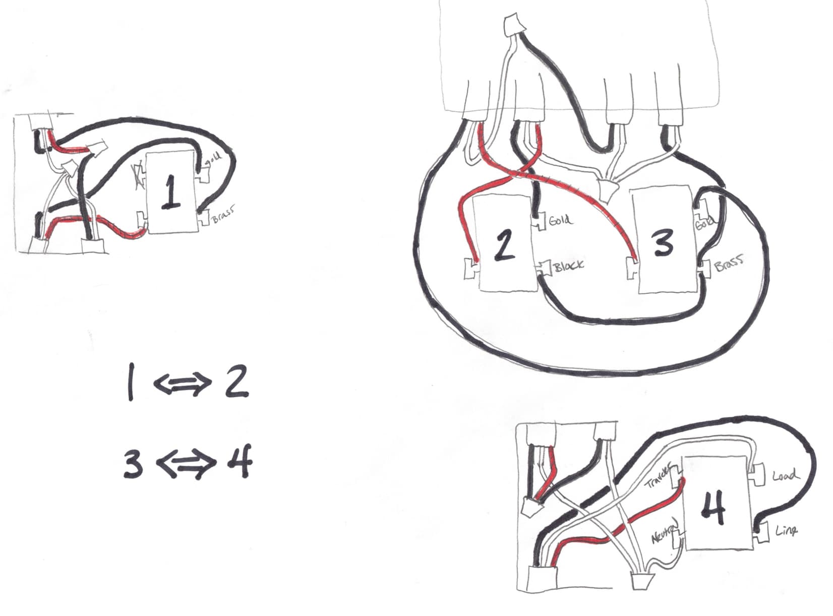
Here is how the wiring is all currently connected:
And the wiring charts I was looking at online are the ones on this page (in the “Multi-Wave (w/Aux Switch)” > “Neutral Wire” > “3-Way Schematics” section). But what I don’t know is which boxes are closest/connected to the 120V power source and which are closest/connected to the ceiling lights.
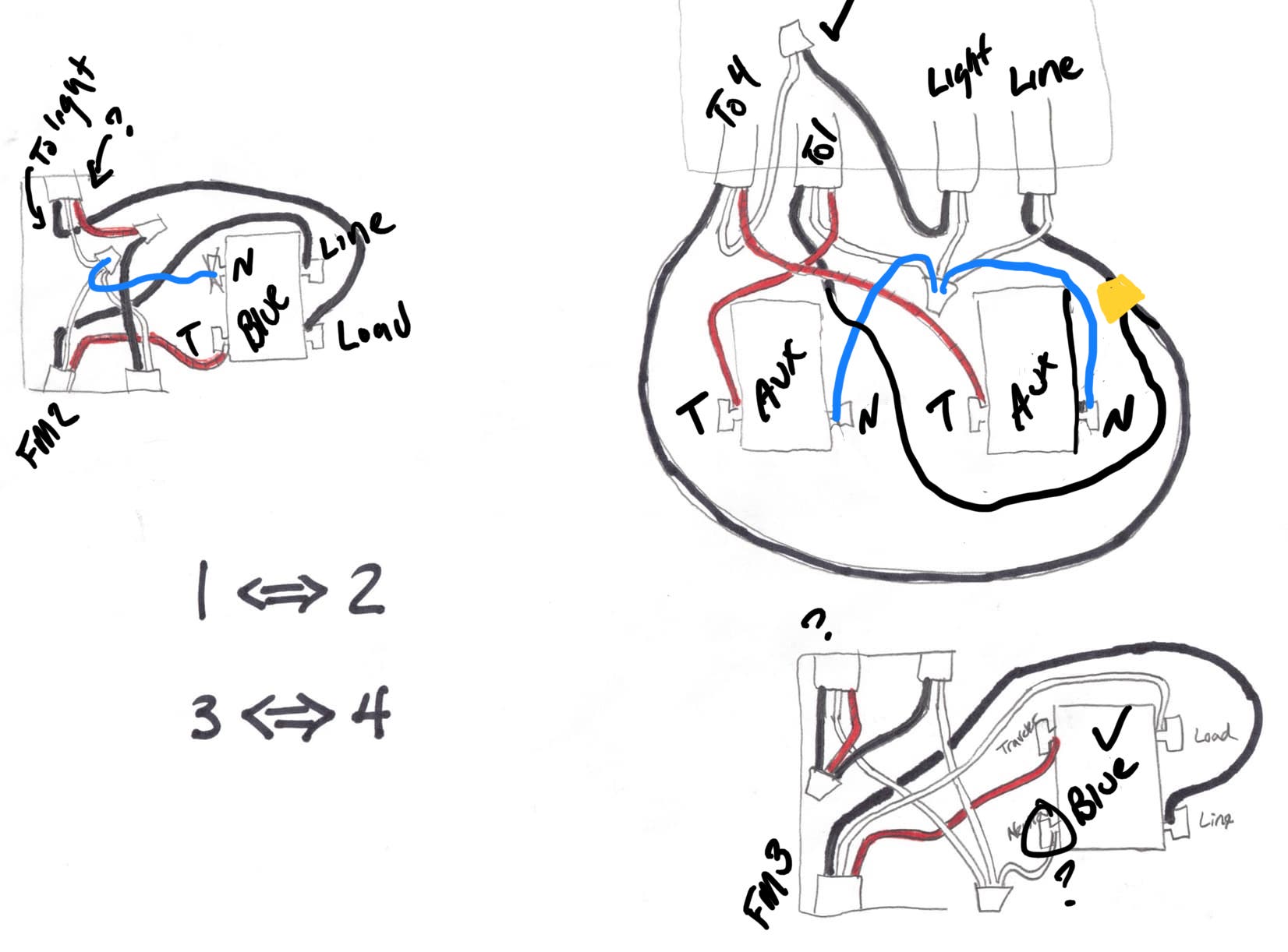
Could you label which screws have COM or common next to it? Should be the Black screw, but want to double check. Right off looks like your line is in the box where switch 2 and 3 are in. We’ll need to rewire it since you want the aux switches here.
So the black screw on switch 2 says “Common”. I don’t see COM or Common near any of the other screws on the other three switches. Also, for what it’s worth, switches 1 and 3 have dimmer toggles, and switch 2 does not have a dimmer toggle. Does that help unravel things? Just let me know if there is any other info I should gather.
Good news, we’ll fix that. Basically the 14-2 on the right side of that box drawn (sw 2/3) is your line supplying power to your lights. May take a bit to draw up but this will be eas(ier).
Yep. Just checked with multimeter. The brass screw in switch 3 reads ~120V - both when the switch is on and off (flipped up and down). I think that makes the right-most 14-2 in the switch 2/3 box the “line,” right?
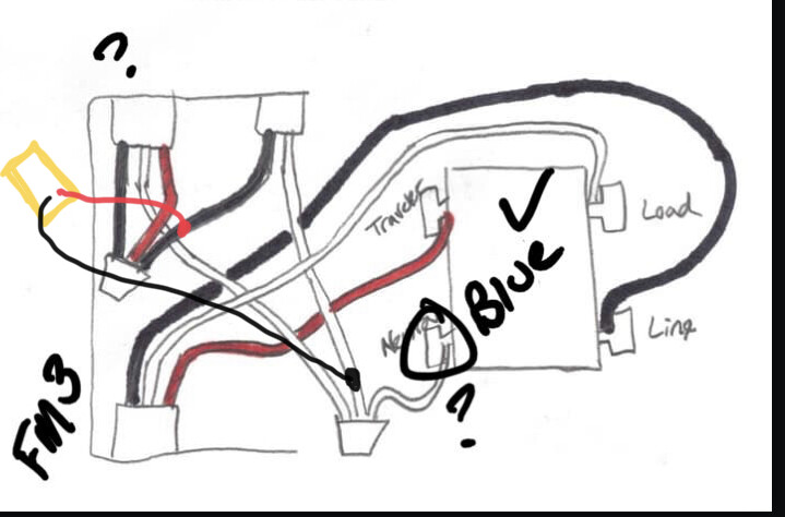
Just to confirm I’m not doing something incorrectly, do I just need to measure the voltage of that screw marked neutral in the red series dimmer, against ground? When I did that, it wasn’t reading a voltage with the red dimmer up paddled and down paddled. Or am I evaluating it wrong?
Measure on the wires I drew dvm leads to. I’m wondering if you stole neutral from another circuit. I don’t know why there would be a 14-2 in this box unless it’s just passing through.
Something is maybe messed up with my existing setup. A second circuit is feeding some of the wires in switchbox 4. I had the ceiling light circuit off, and was unscrewing the caps, and I can tell that some of the wires are still “hot.” It seems to be related to an outlet recepticle nearby. I think maybe this switch used to control a floor lamp that plugged into that receptacle, and was repurposed when the ceiling lights were later added?
When I use a no-contact tester, I can tell that the white from the 14-2 is hot, and the black from the top-left 14-3 is hot. Does that help at all?
Interesting. It’s legal to have another circuit in the box so that may be the case. If that is the case, we can’t use the neutral for the 2N1 and will have to be a non neutral setup.
Non contact isn’t the best method to check. I would’ve expected the BLK from the 14-2 and BLK & RED from the upper 14-3 to be hot.
Edit: same for switch 1. Is the 14-2 hot when you open the ceiling light circuit breaker?
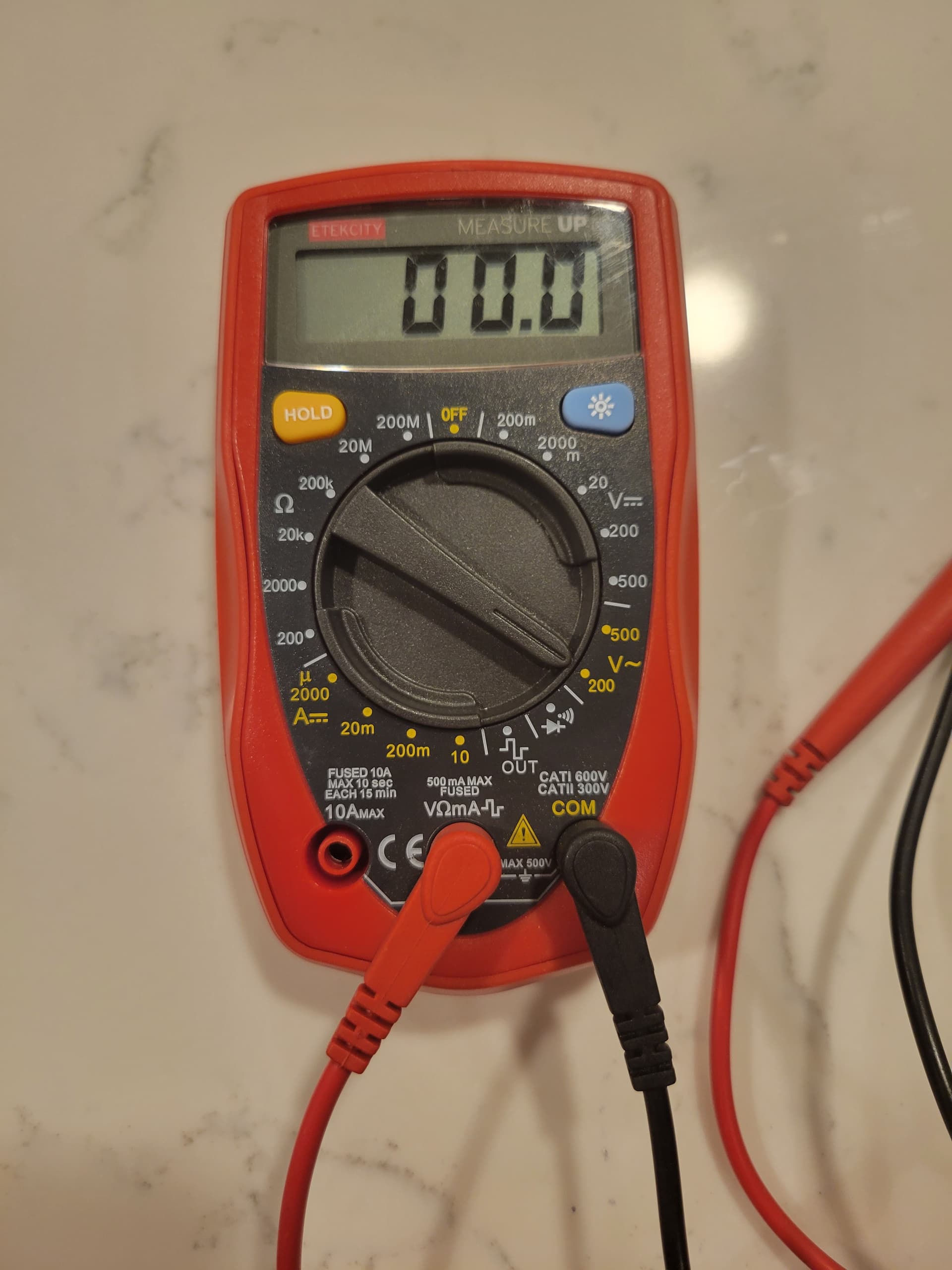
So when I’m doing the multimeter check your drew above, am I supposed to be using the 200 V AC setting? If so, when I do that - I don’t get a reading, but the lights flicker when the black probe touches the white wire from the 14-2. (Apologies, I’m a noob with a multimeter)
So I did some more multi meter measurements in switchbox 4 while the ceiling light circuit is off.
As expected, the 14-2 black and white both measured 0 compared to it’s ground (since the circuit is off).
But the top left 14-3 shows it’s black wire to be hot (120V measured against it’s ground). It’s white shows 0 and the red shows 0.3. Does that make any sense or help at all? I have not found what breaker switch controls that top left 14-3.
Yep, all wires for the 14-2 and all for the top left 14-3 have been separated out of their respective wire nuts and are free-floating/not touching anything else. Should I just do the same with the bottom left 14-3, and get the red series dimmer out of the box?
Edit: I’ve also confirmed that an outlet near switch 4 and an outlet near switch 1 are off while the ceiling light circuit is off. So it seems the ceiling lights were a later addition to the house and are tied to those outlets.
 ), and I want to replace it with a Blue 2-1