Hello, I have a very basic understanding of electricity so I may be in over my head. I was hoping someone could look at these pictures and help me determine if I can DIY it or if I should hire someone (ugh). Thanks in advance.
Without exactly knowing what you are trying figure out or which switch(es) you are focusing on:
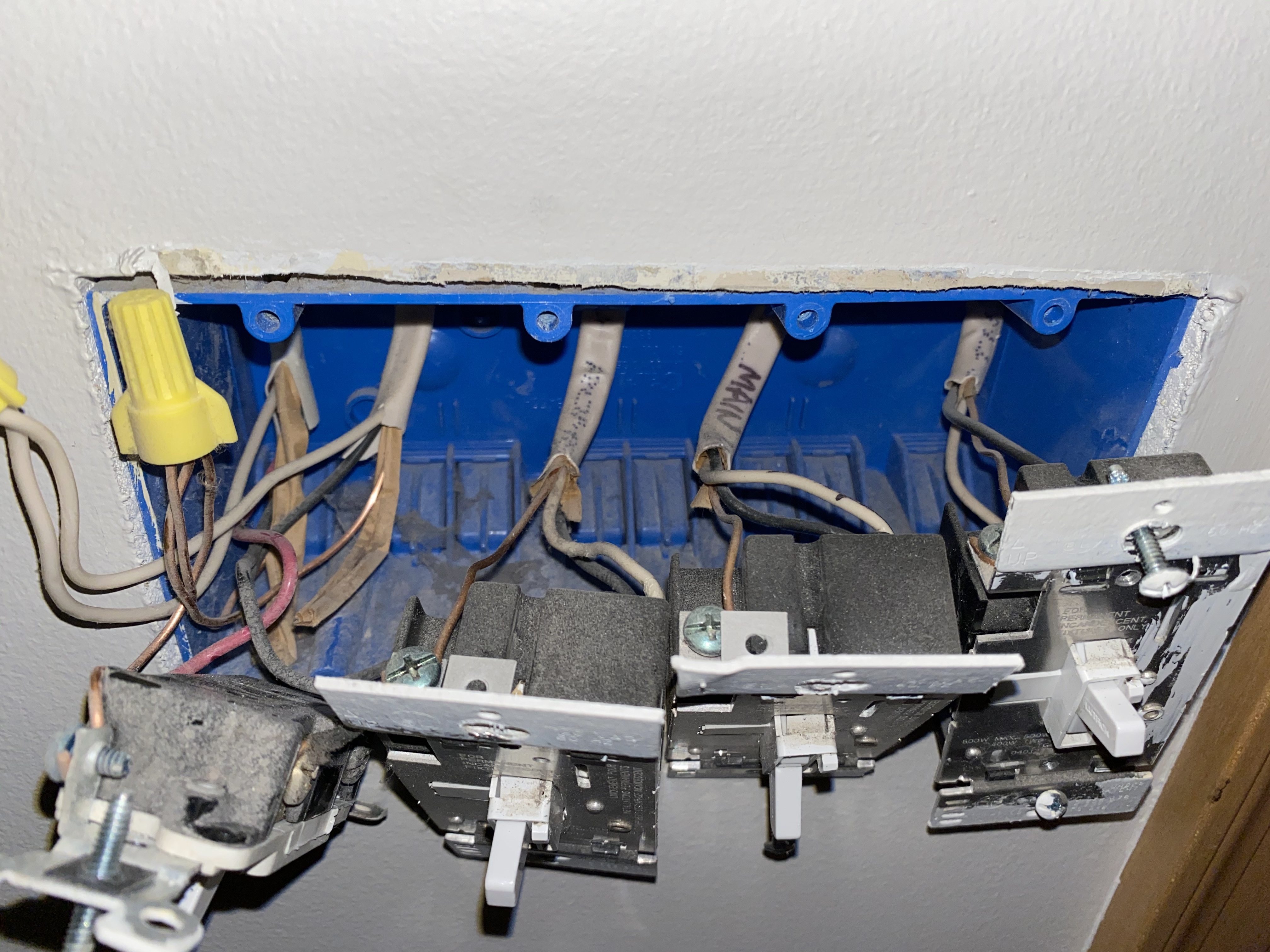
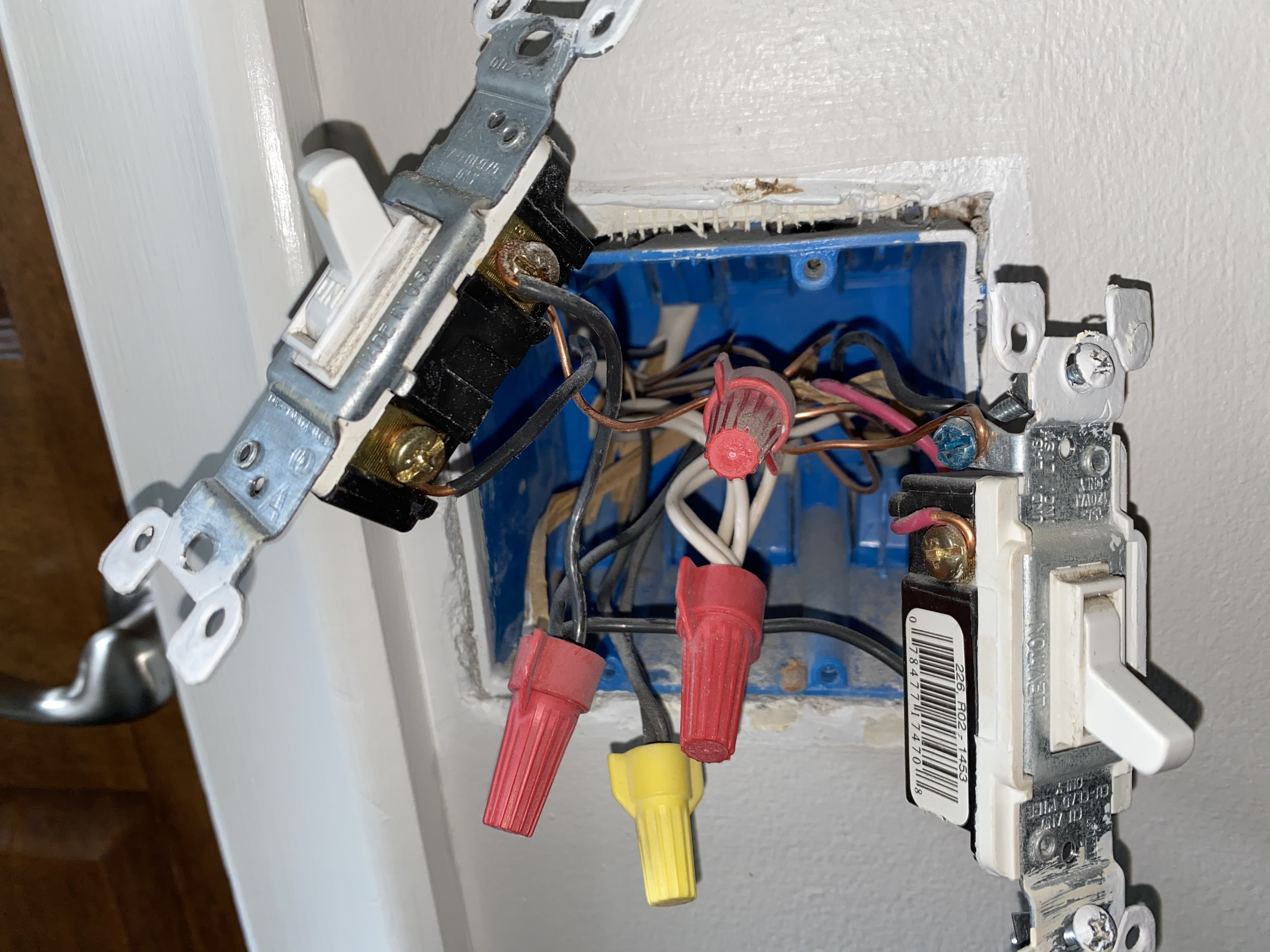
- In the first pic, the three toggle switches on the right are non-neutral 2-way legs.
- In the first pic, the switch on the left is one side of a 3-way, although I can’t say which side without some testing and seeing the other box.
Thanks for the response. I am hoping to install the lzw-31sn.
Which position? All four?
First: What are you trying to do?
What are these existing switches (what kind, I can’t tell from the picture), what do they control, and which ones are you trying to replace with Inovelli switches?
Second:
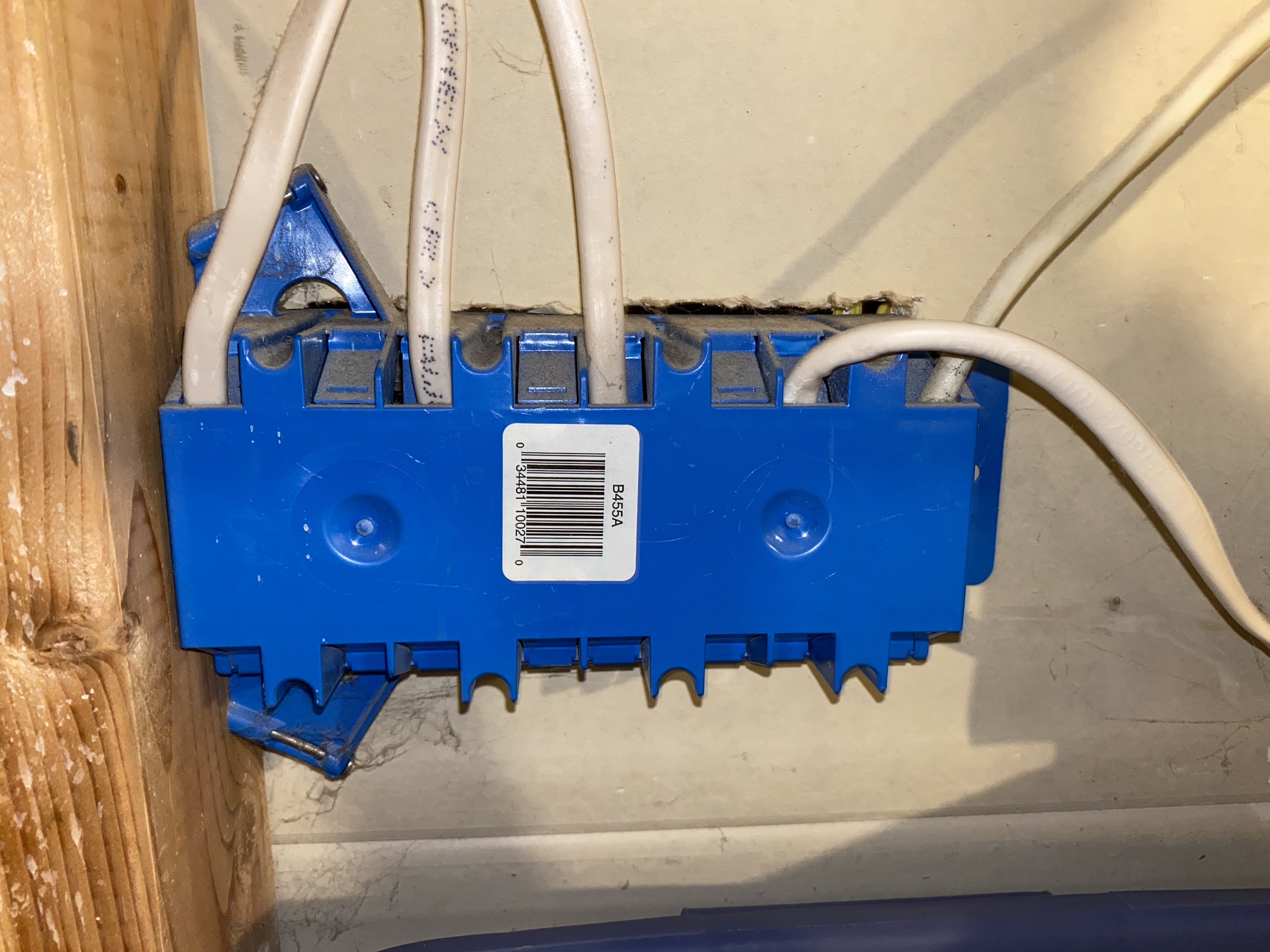
It looks like you’ve got access behind the junction box, which is a luxury I rarely have when working on my house. In the worst case, you could just follow the cables coming out the back of the box and see where they go. That should tell you a lot more than my guesses below.
Third: 3 switches on the right
On the right, three switches appear to be connected to only ONE cable. Usually you have TWO cables:: one coming from the load center / breaker panel, and another going to the load (e.g., light fixture).
Although there are other possibilities, when I’ve encountered this in my house, it is a switch controlling a switched outlet. The cable comes to the switch directly from the outlet, with the white connected to the “hot” wire in the outlet’s junction box, and the black connected to the “hot” pin in the outlet itself. There’s no neutral because the builder/electrician was too cheap/lazy to pull 14/3 instead of 14/2 (so the white could be neutral, and the “hot” could come in and out on the red and black wires). When a white wire is used to carry something “hot” rather than “neutral”, it is supposed to be marked, usually with some black electrical tape, but that hasn’t been done. Whoever did the wiring at my house didn’t do it either. I positively hate that kind of laziness, but cheap builders will be lazy until code forces them to do otherwise…
Fourth: The switch on the left
I can’t see clearly what’s happening here. It looks like the leftmost switch is connected to two cables, and the neutrals and grounds are each bundled and connected by wire nuts – all of this is what I would expect for a normal single-pole light switch connection. But because I see a red wire instead of just black wires, we would need to see exactly where those red and black wires are coming from (which cables) and where they are going to (which terminals on the switch).
Fifth: Be careful
Finally, if this job is big enough to have the walls open, you’ll want to consider whether it’s big enough that you need to have an inspector come check your work afterwards. If so, you’ll probably want to hire someone. The dangers of electricity are not just the obvious ones of getting zapped (either while doing electrical work, or from a badly wired device). Bad wiring can also start fires within the equipment, the junction box, or behind the walls (which is a real nightmare). Note that the The National Electrical Code is produced by the National Fire Protection Association…
I’d take your advice there. I could replace all 4 with dimmers but that seems like a waste. They are controlling cans in my basement that I believe are permanent as they don’t appear to have bulbs.
The three on the right look like they’re dimmers. Do you use the dimming part or just us them as switches? It sounds like the cans you are describing are LEDs. Only some LEDs are compatible with Inovelli dimmers, so that’s a tough call. If you knew the brand you could check the compatibility chart, but usually it’s trial and error.
The switch on the left is paired with at least one other switch. I wasn’t clear when I referred to the other side, but I meant I’d need to see a pic of the other switch. We need to do some testing to see if the Inovelli can go in the box you posted pics of or in the other box.
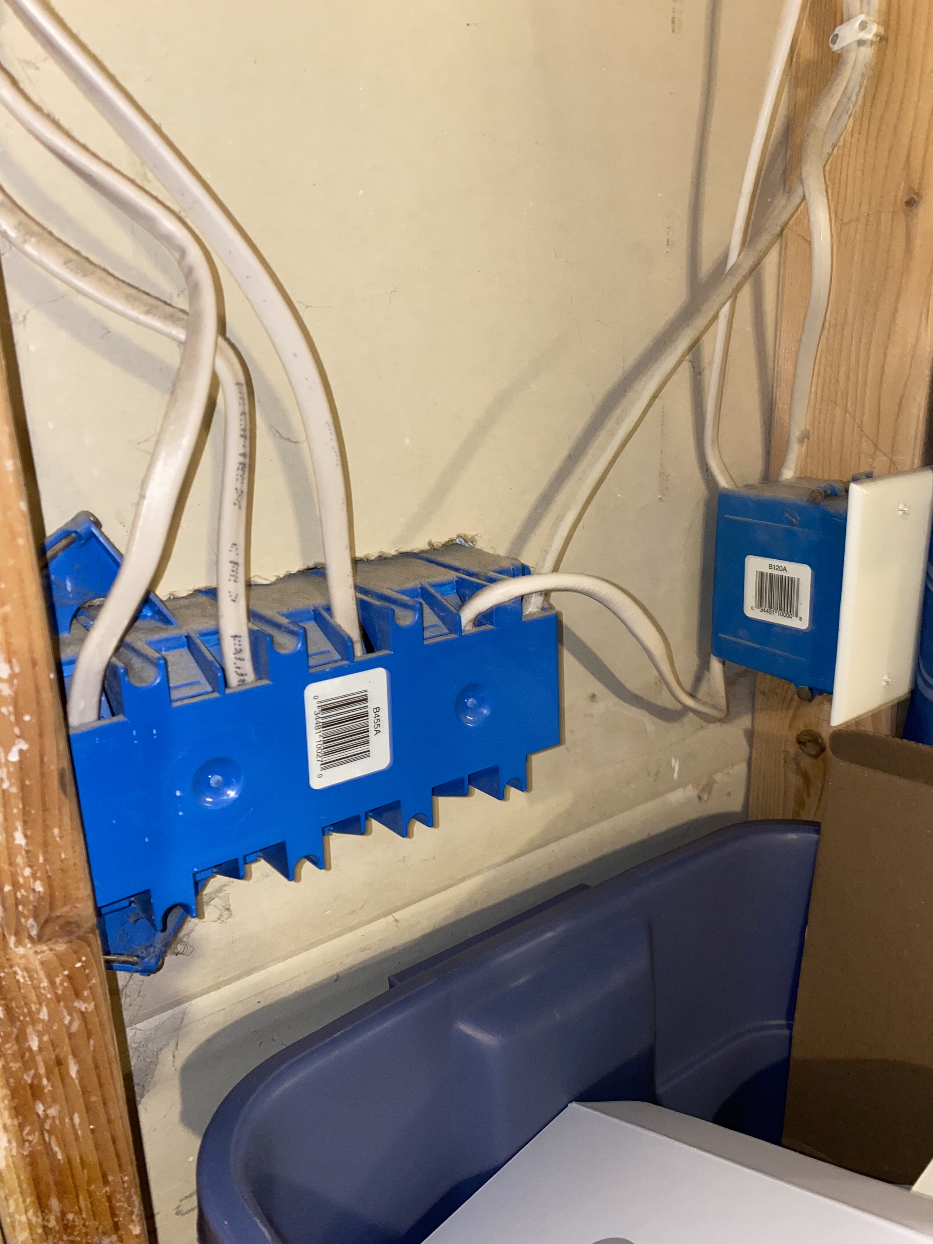
I do use the dimming part but not very often because the dimmer doesn’t work super well. Does it have anything to do w this small box?
How would I determine where the other switch is?
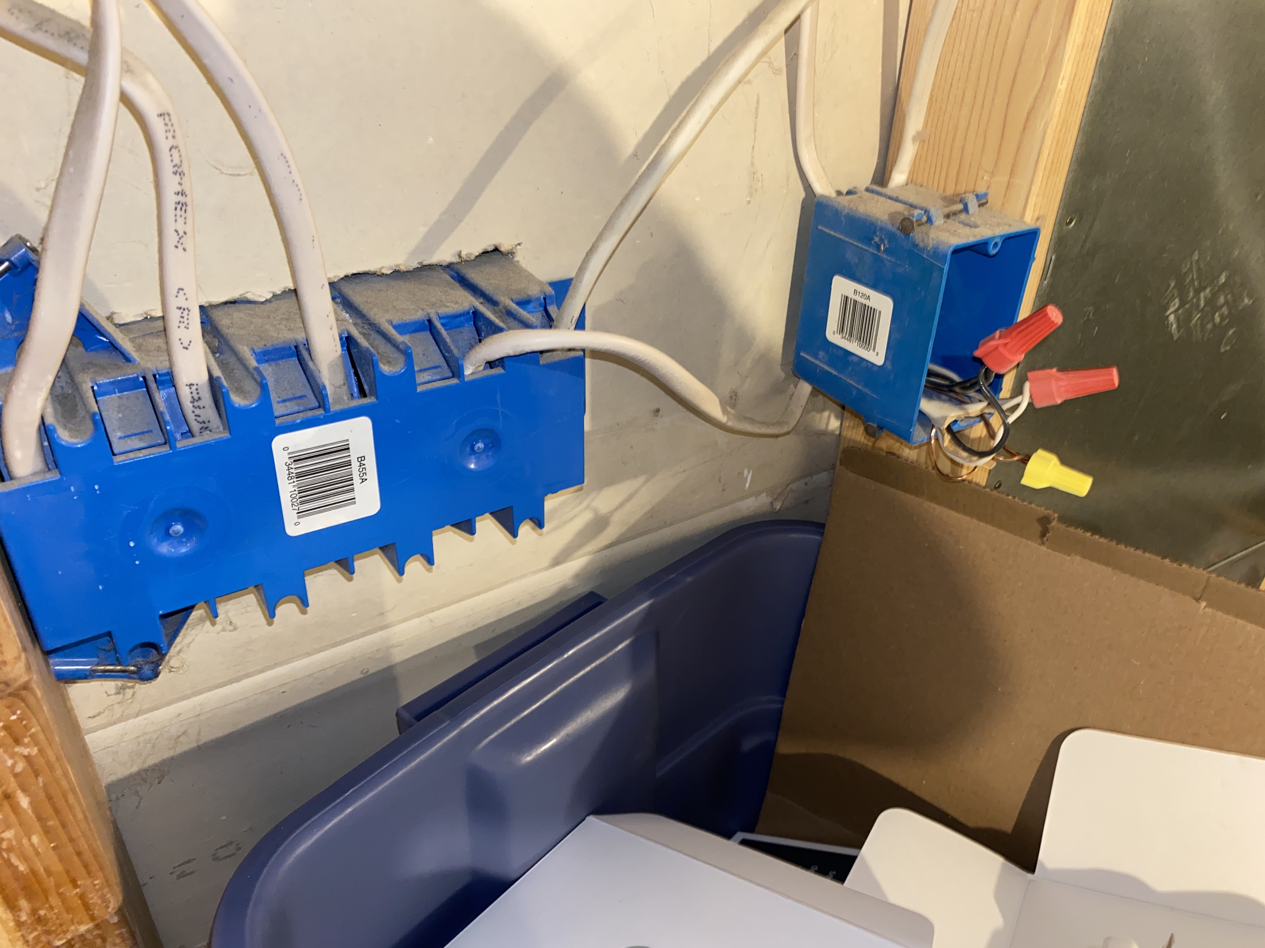
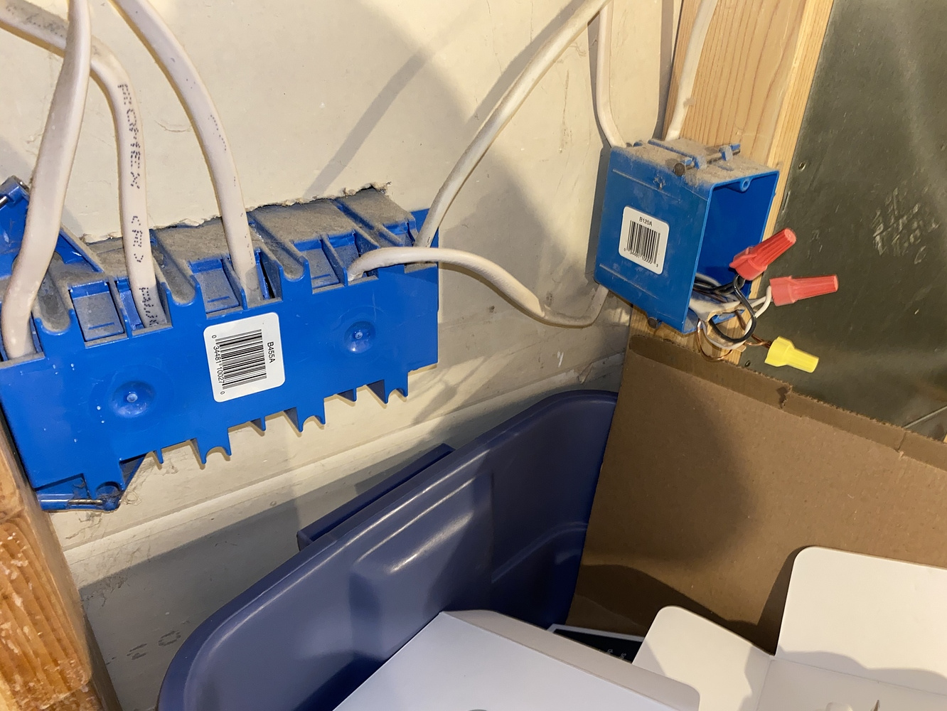
That box you just posted a picture of is just a junction box. I’m guessing that is a hot feed which is being split to provide power to your 3-way (far left) switch and is also providing power somewhere else. One of the Romex going into the top is probably a hot and the other going in the top is providing power downstream to something else. The one going out the bottom is providing power to the 3-way switch on the far left. (Subject to testing with a meter.)
As far a finding the other switch(es) . . . I’m guessing you’ve walked around flipping other switches and can’t find something that operates the same light(s) as the switch on the far left? It’s possible the switch was removed or never put in.
Looking at the last picture you posted of the back of the multi-gang box, the 3-wire Romex is the Romex all the way to the right. It is the one that is more round than the 2-wire, which is flat. Can you follow that 3-wire and see where it goes? I don’t know how much of your basement is exposed.
Is that switch also controlling cans or something else? Think about where logically another switch would be. Typically you need a switch at entry points to a room or perhaps the top of the stairwell. You have to find where that 3-wire terminates on the other end because your light is probably connected on that other end.
Yep, not sure how I forgot this but that same switch is connected to the one at the top of my stairs.
Great. If you can pull that other switch out and take pictures we can figure the remaining piece.
Also, do you have a volt meter? We need a couple tests to confirm things.


Those pictures are about the best I could do. Do they work for you? Also, I have a Klein voltage tester, would that do? I could borrow a voltage meter from my neighbor if need be.
Which switch is related to the 3-way? I’m not sure which one we’re working on. I’m thinking it’s the one on the right but want to confirm.
A voltage tester isn’t sufficient. You need a meter that can measure voltage between two conductors, so if you could borrow one, that would be great.
I just borrowed one. The 3 way switch is the one on the right side with the red wire. I believe that red wire flows between the 2 switches.
Ok, we need to find the source of the hot. I was thinking it was downstairs but from what I’m thinking I believe it may be upstairs.
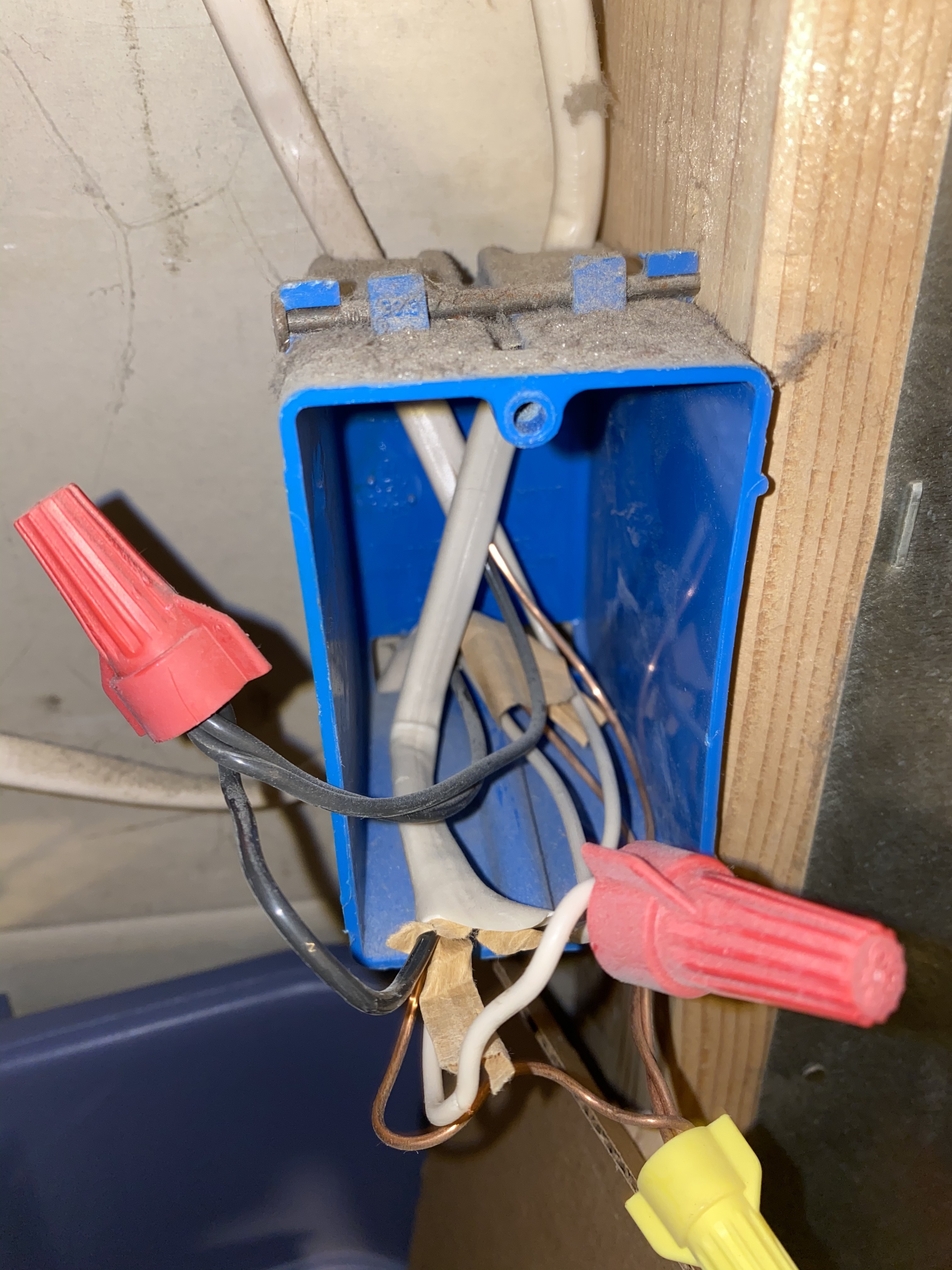
In the upstairs box, please confirm this as I can’t see the right side of the switch:
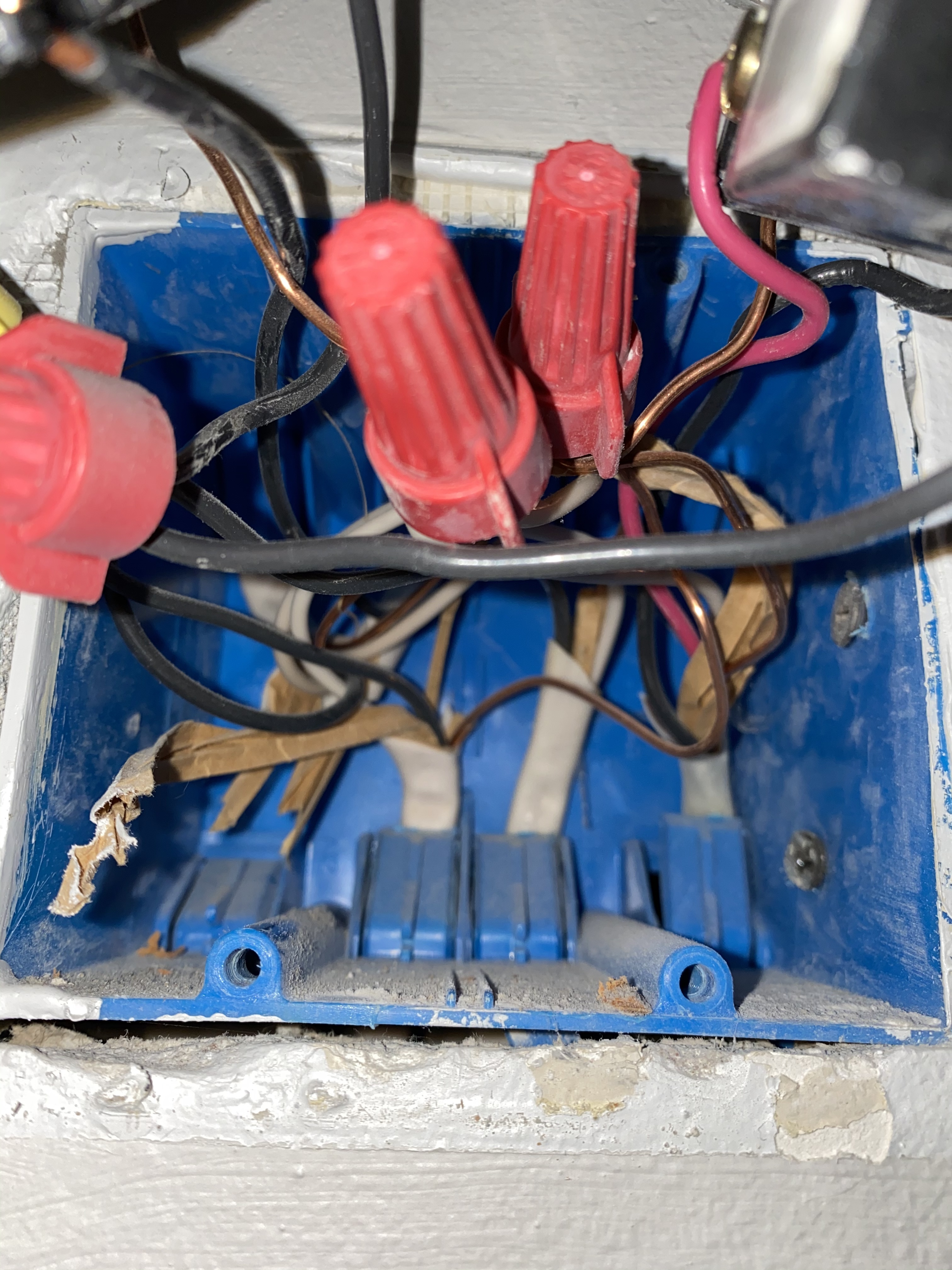
- The conductor on the black screw is a black pigtail connected to two other black wires with a red wire nut.
- The two conductors connected to the two brass screws on the switch are red and black and are part of the SAME 3-wire Romex. (That’s 3 wires plus a ground.)
- The white in that same 3-wire Romex is connected to the white bundle with the red cap.
I am currently waiting on some work that is being done to my house to go open that box up and confirm what you sent so thanks for being patient. With 2 kids running around I can’t just leave it open! Thanks again for all your help so far and I should have an answer shortly.
1 Like
I just confirmed that everything you wrote is true.
Ok, one question and then a test. I am thinking that your power is supplied at the top of the steps and the lights are powered via the switch downstairs. If that’s true, the power to the light goes into that junction box you posted a picture of. That is a bit unusual as lights are usually daisy-chained. Do these switches control multiiple lights? From the junction box, it looks like the power to the lights is split in that junction box. Does this make sense?
I think power is being supplied to the upstairs box. To test, remove the black wire from the black screw on the upstairs switch. That should be that short jumper connected to the other switch. Also temporarily unscrew the wire nut from the white bundle. Using a meter test between the black wire you removed and the white wire. I am expecting 120V. Perform this test with the downstairs switch in both positions. If I am correct, you will get 120V with the downstairs switch in either position.
Once you’ve completed the test, put the wires back as they were so it’s functioning again. Then repeat the test downstairs. Remove the black wire from the black screw. Temporarily remove the wire nut from the two whites (in the left on your picture) and test between the black and the white bundle. Test with the upstairs switch in both positions. I would not expect 120V regardless of the upstairs position.