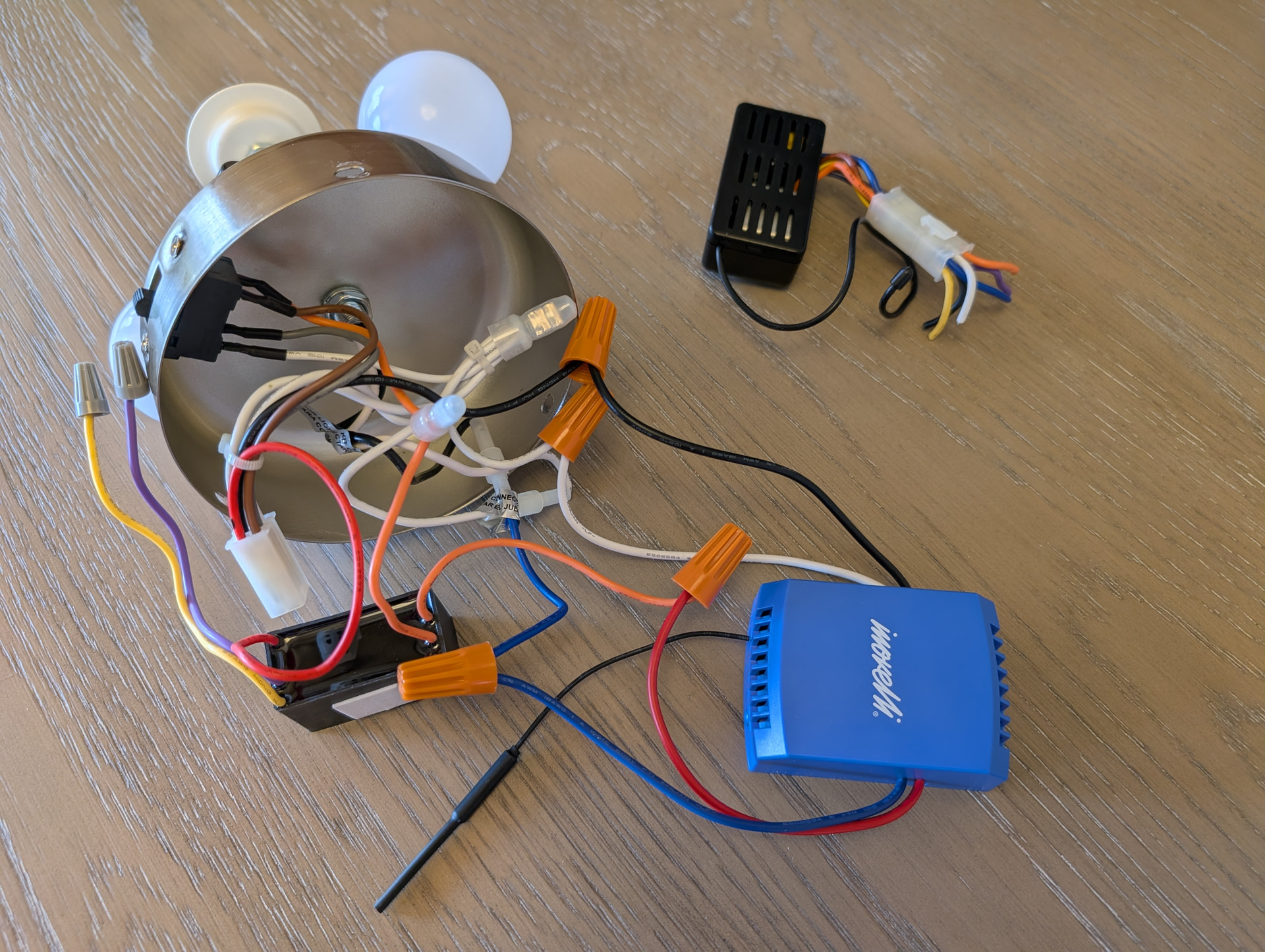
I have Harbor Breeze Crosswinds ceiling fan from Lowes (https://www.lowes.com/pd/Harbor-Breeze-Crosswinds-52-in-Brushed-Nickel-Indoor-Ceiling-Fan-with-Light-Kit-and-Remote-5-Blade/50261529) I am trying to wire Blue Smart Fan & Lights Canopy Module. I know where the white, black and blue wire go. Just not then Red/Fan wire. I am reading the blue smart fan module has a built-in capacitor. Should I remove the capacitor as it is doing “double duty?” Details below. Any help would be great.

Black and white wires to the fan.

Taking apart the “switch cup” below the motor housing unit. There is a black and white wire that come from the top. There is a red, brown, gray and white wire (pretty sure white is neutral; brown and gray seem to have something to do with the fan reverse switch.) I am not sure about the red wire (assuming this is the fan motor wire.)
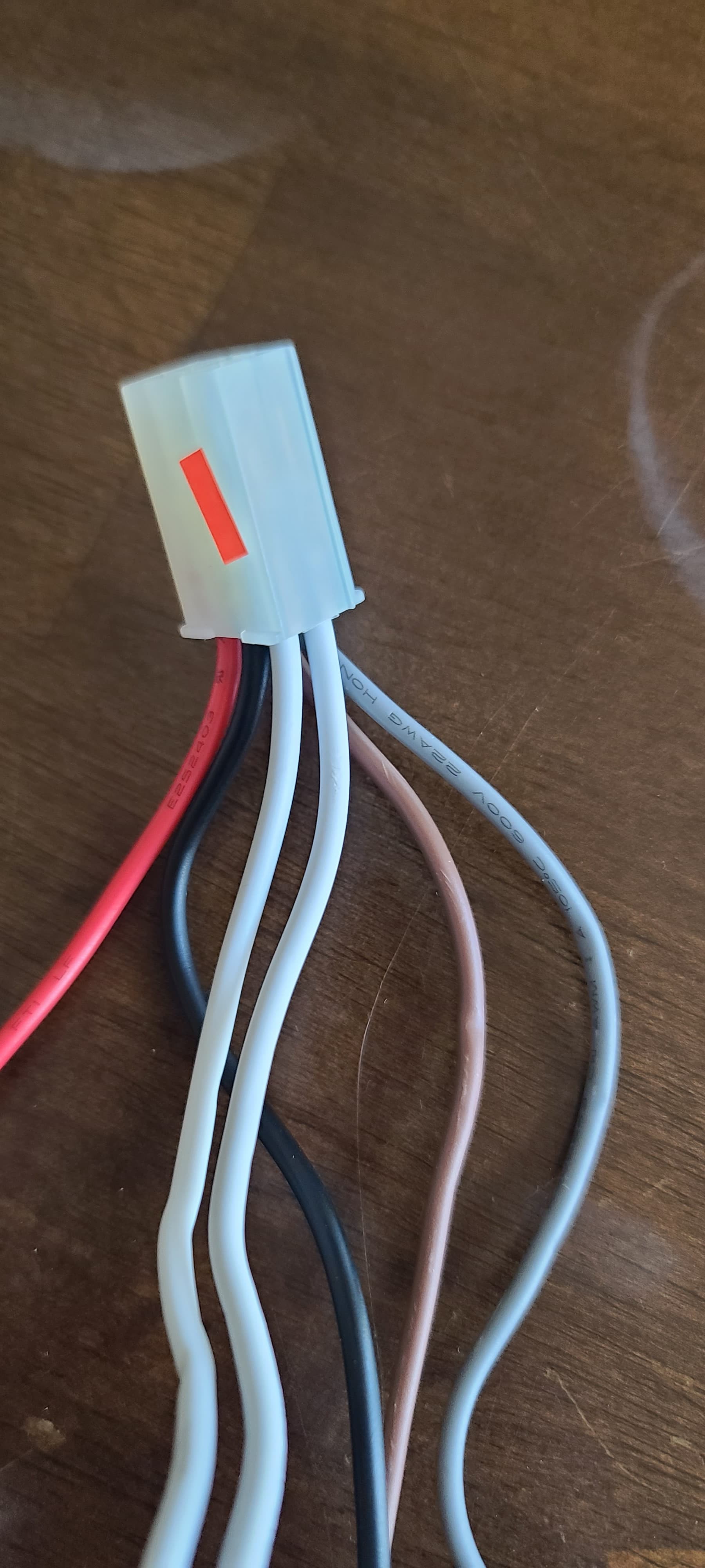
This is the next connection. Again, white = neutral x2, black = line, brown and gray go to fan reverse switch and red goes to capacitor.
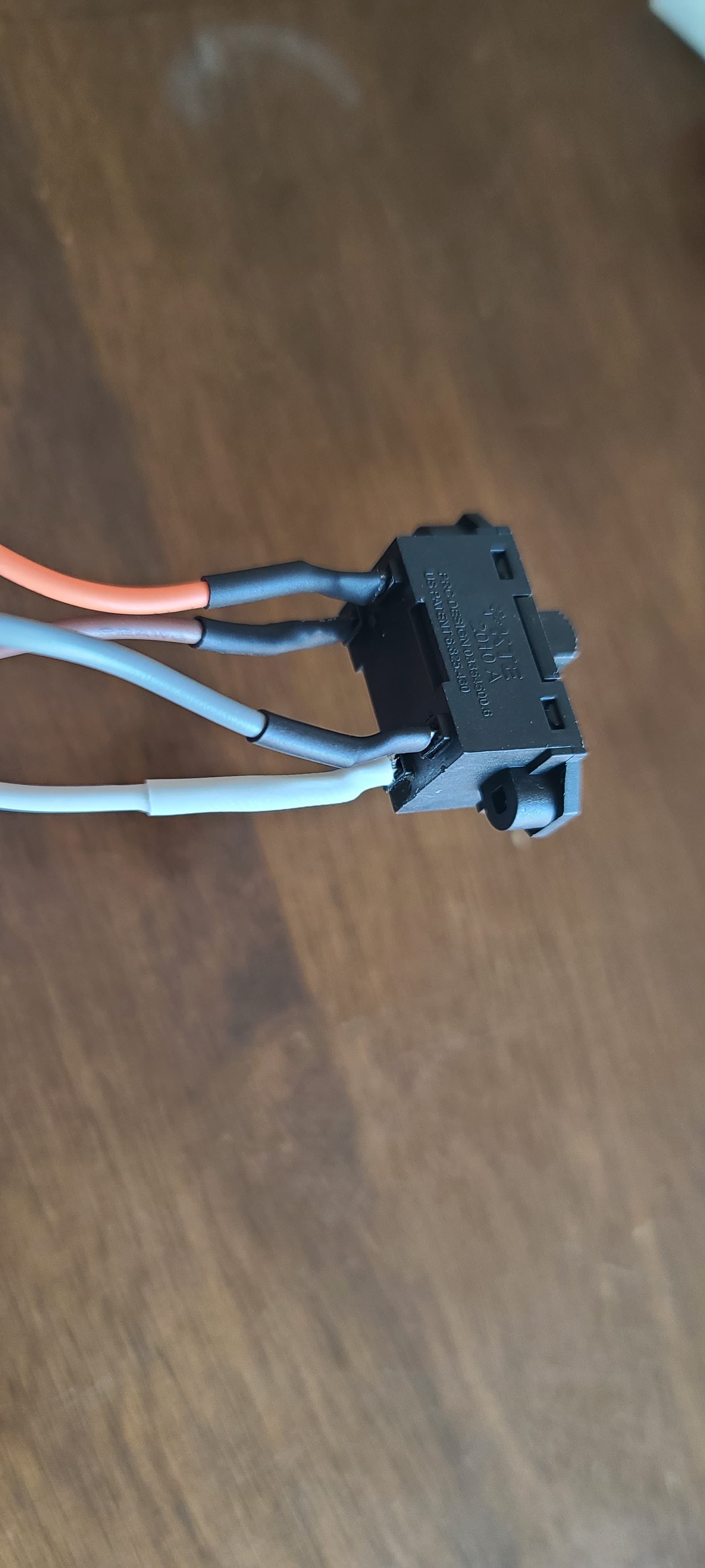
This is the switch for reverse fan direction for winter vs. summer. When to the left, orange wire (from capacitor) and gray wire have continuity. When to the right, orange and brown wires have continuity. White is still neutral.
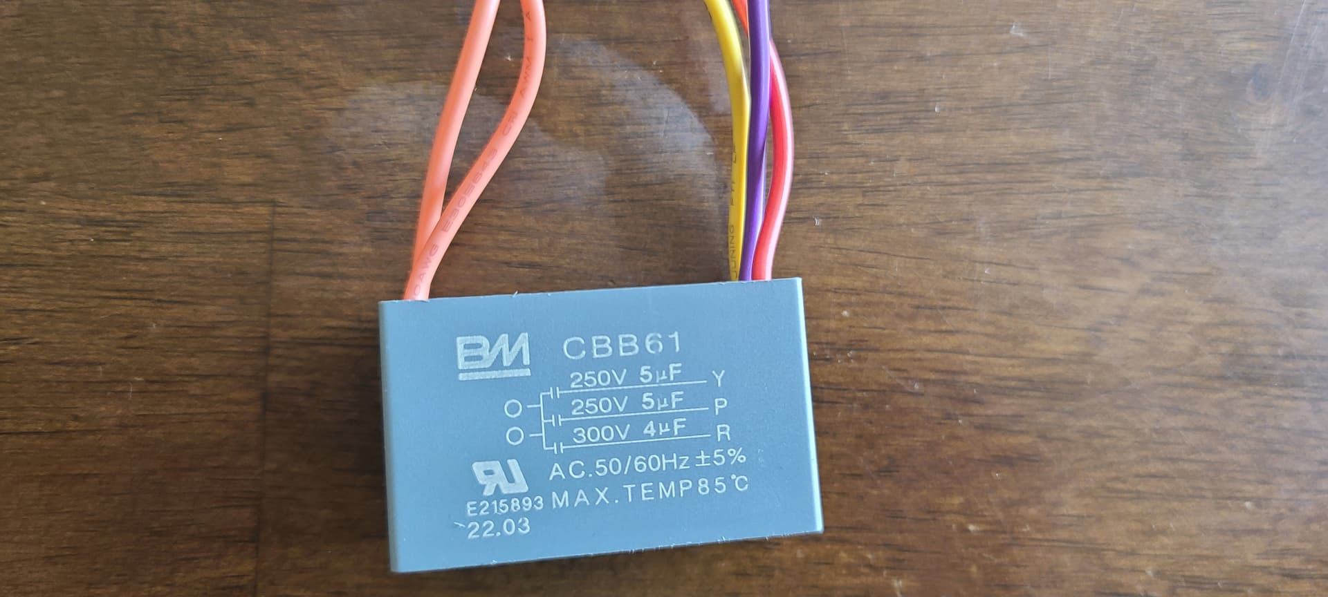
This is the capacitor:
Orange1 wire coming from reverse switch into capacitor and out to orange2 wire (goes to the wireless remote module, changes wire color to gray) and connects to FAN HI.
Yellow wire goes to wireless remote module and connects to FAN MED
Purple wire goes to wireless remote module (changes wire color to blue) and connects to FAN LOW.
Red wire leaves capacitor for the fan motor housing - not sure where.
I’m assuming if i connect line to orange wire (that will mimic FAN HI.)
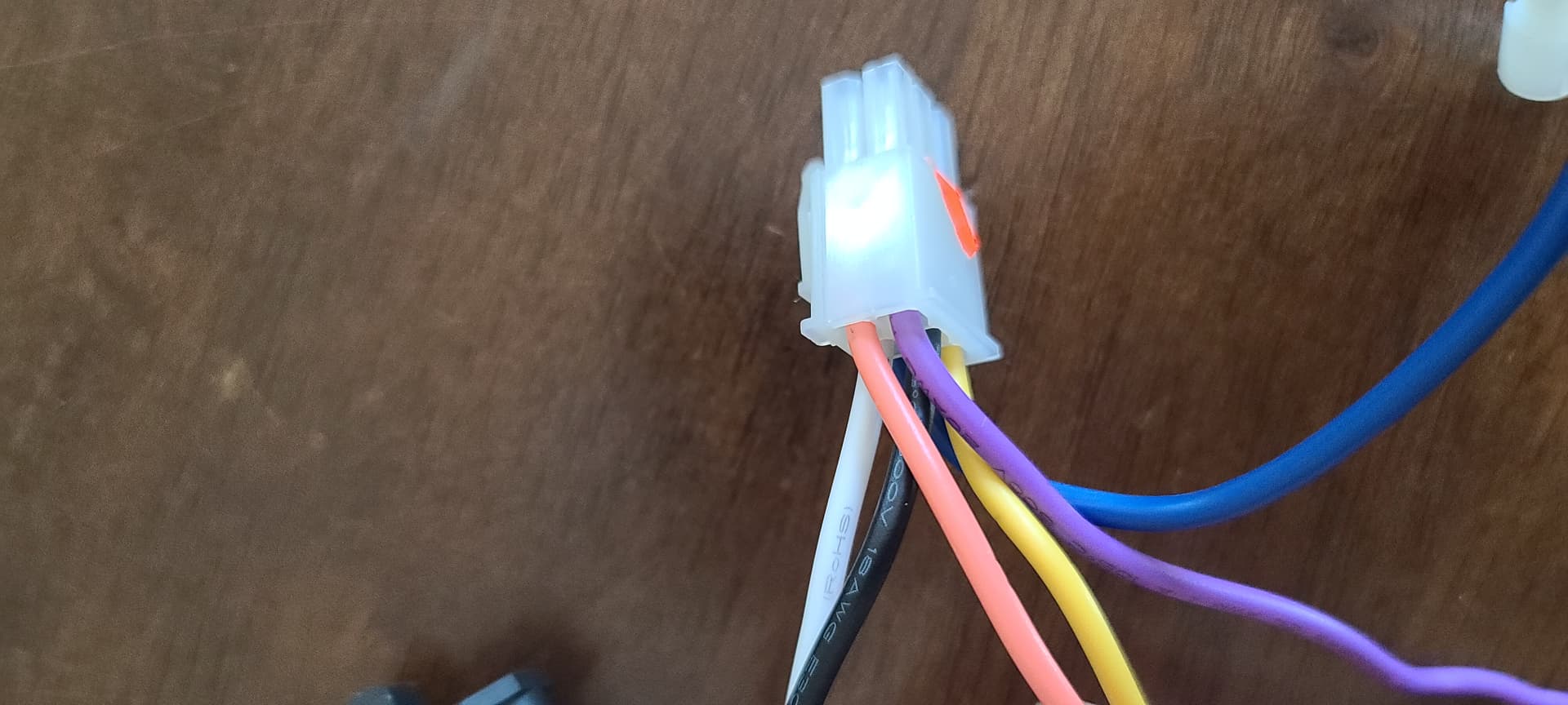
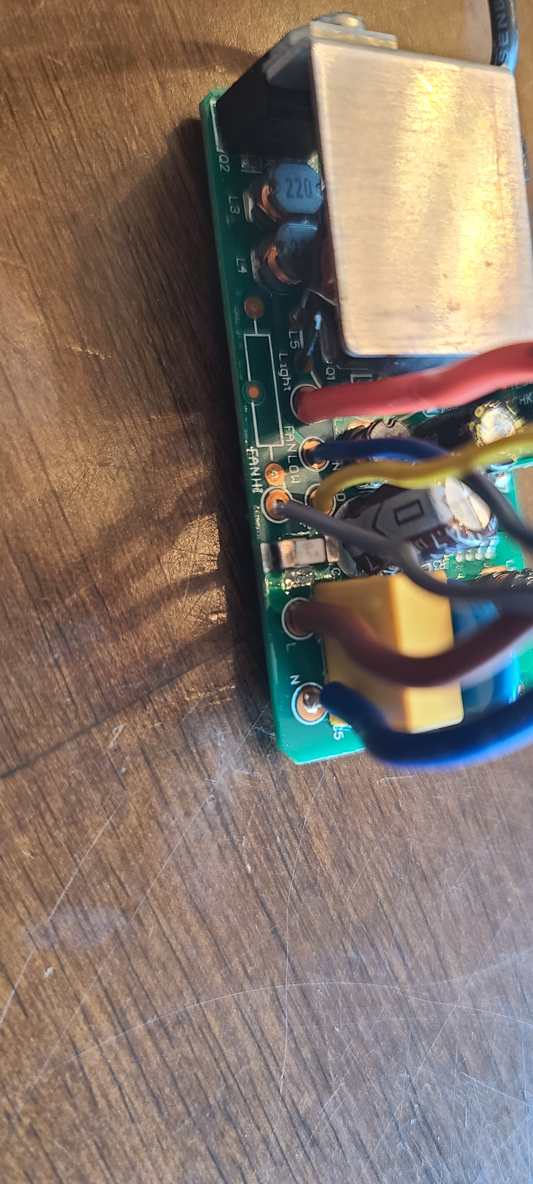
This is the wireless remote module.
Black goes to Brown and L (line) on the circuit board.
White goes to Blue and N (neutral) on the circuit board.
As stated above, purple > blue > FAN LOW, yellow (stays yellow) > FAN MED, orange (from capacitor) > gray to FAN HI.
The light is the orange wire on the wireless remote module that changes to blue at the plug. That makes sense to connect to the BLUE wire of the Inovelli Module.
Any thoughts would be helpful!
EDITED to make URL resolve . . . Admin