@harjms If the OP can confirm what I posted, I see what he has. Line and Load in this box. 3-way with the line being sent over the black to the other switch, wherever that is/was.
The line is probably going to come from the bundle of BLK wires all connected together (it probably continues to feed switch or outlets near by). BUT I would’ve thought Set 1 is your traveler from another box in a line/load setup. This would be the last switch in line to power up the light, so that the “COM” is the load.
But then I see your Set 4 was connected to the common, so it could be powering up the switch in line.
I’m not too worried with set 2 or 3 as this seems to be just another junction box for those wires.
Maybe this box has two sources? It’d be worth getting a multimeter to check.
2 Likes
@Bry - Concur, but where is the question!
I’m not sure what you’re saying. Please look at my description and let me know if what I described is correct. I can’t see well enough into your box to tell.
1 Like
It shouldn’t matter. To close off the other end, you can just wire nut the common and a traveler together and cap off the other one. It’s simulates the switch that was there as “stuck” in one position.
I’m pretty sure the line and load is in this box so it’s simple. Just can’t see into the box enough.
2 Likes
Definitely, but where ever this junction box is, should be covered and accessible. You can’t leave a dead ended wire not accessible.
Yep, it could be in another box that has been repurposed. It could also be buried, which of course is wrong. Or the OP may just not know where it is.
Plus it’s not your house, lol.
Sorry guys, I have a new account and it capped my replies for first 24 hours, just got it unlocked. @Bry I posted a list and catalogued all of the sets of wires coming into the box at the same time you asked about the wires looks like, I don’t think either of us saw each-others comment at the time, I think I commented/tagged you on the wrong post that outlined it, that’s my bad. I think it’d be helpful instead of the pictures (sorry those were blurry, appreciate you taking the time to comment on them).
I’m also looked into a light switch that shares the same wall as the switch in question (other side of the wall), that has two black wires attached to the bottom of the switch (line?), could this be the culprit of the dead end you mentioned? This other switch controls one outlet, no light bulbs. They share the same circuit breaker…
(Side note, I’ve since installed a Red dimmer switch at the separate bottom of the stairs switch I had shown you guys yesterday, thanks for your help with that one confirming the normal wiring)
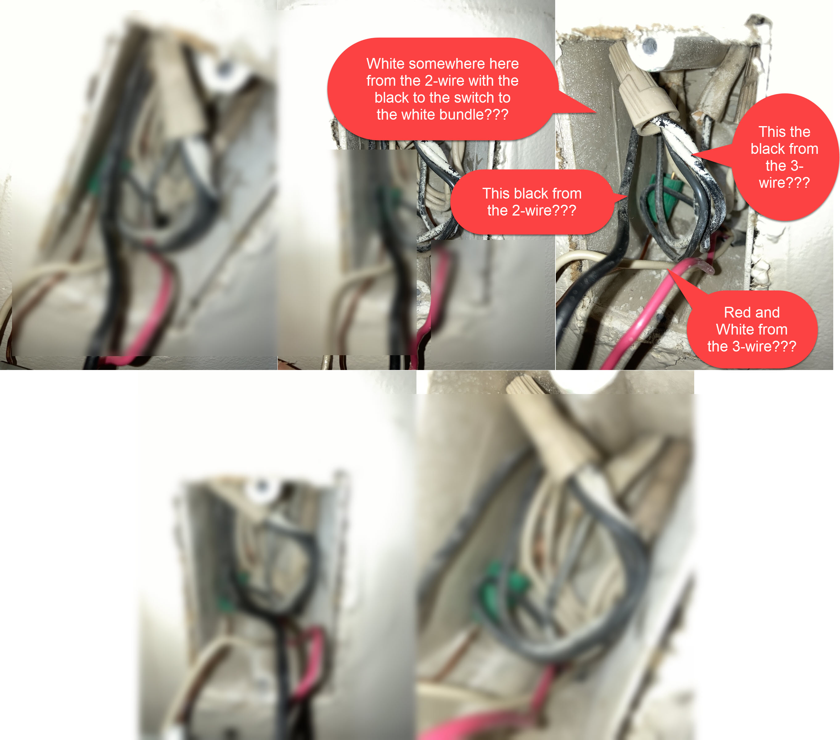
@bry from what I can see, there are 4 ‘sets’ of wires coming into the box, each has a black/white/copper, and 1 set has a red (the one coming from the bottom of the box, ‘set 1’).
Set 1) coming in from the bottom of the box, is a set of 1 black, 1 white, 1 red, 1 copper. The copper from this set goes to a cap with all of the other coppers, which has a line that comes out to the switch. The white and red from this set attach to the old switch in my first pictures. The black from this set is capped with the black from sets 2 and 3.
Set 2) coming in from the top of the box, a set of 1 black, 1 white wire, and 1 copper wire. the black capped with the black wire from set 1 and 3. The white wire capped with 3 and 4 (neutral?), and the copper capped with other copper wires from all sets (which shoots out a wire to the switch)
Set 3) coming from top of the box, a set of 1 black, 1 white, 1 copper. The black capped with the blacks from set 2 and set 1. The white capped with the whites from Set 2 and 4, the copper with the same cap of coppers as the others.
Set 4) Coming from the top of the box, a set of 1 black, 1 white, 1 copper. This black is the black that went to ‘common’ of the original switch, which I’m hearing is the ‘line’, and then the white bundles with the whites from set 2 and 3, copper bundles with the other coppers.
Hope this helps!
That’s. Here is what you posted condensed. Give us a bit of time to diagram and we’ll figure out what you have.
There are 4 Romex coming into the box, three 2-wire (black/white) and one 3-wire (black/white/red).
Set 1) coming in from the bottom of the box, is a set of 1 black, 1 white, 1 red. The white and red from this set attach to the old switch in my first pictures. The black from this set is capped with the black from sets 2 and 3.
Set 2) coming in from the top of the box, a set of 1 black, 1 white wire. the black capped with the black wire from set 1 and 3. The white wire capped with 3 and 4 (neutral?)
Set 3) coming from top of the box, a set of 1 black, 1 white. The black capped with the blacks from set 2 and set 1. The white capped with the whites from Set 2 and 4.
Set 4) Coming from the top of the box, a set of 1 black, 1 white. This black is the black that went to ‘common’ of the original switch, which I’m hearing is the ‘line’, and then the white bundles with the whites from set 2 and 3.
1 Like
@Bry You’re the man! Really appreciate it, going to upload a picture/catalogue of the switch that shares the wall with this one, which has the extra black wire, in case that’s helpful. Thanks again.
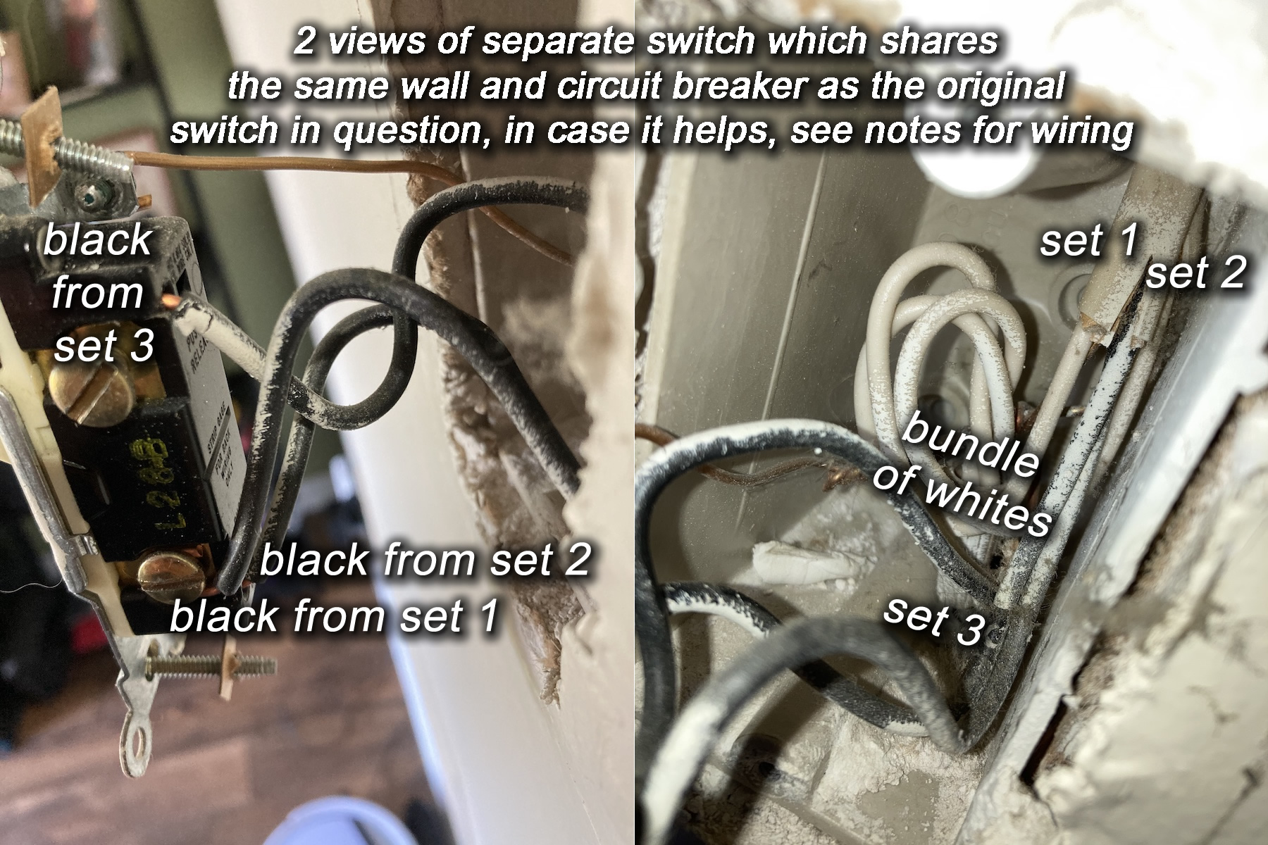
@Bry @harjms @timrudd12 attaching pics/notes of a switch that shares the same wall as the original switch in question, in case it helps:
Based on what I’m hearing, the terminology for incoming bundles I have are ‘Romex’ (?), and if so , here is the breakdown of this switch that shares the wall with the original switch in question.
3 Romex coming into the box, all three 2-wire (black/white)
Set 1), comes in from the top of the box, white goes to bundle with the other two whites from Set 2 and 3, black goes to the bottom of the switch (with another black from Set 2)
Set 2), comes in from the top of the box, white goes to the bundle with the other two whites from set 1 and 3, black goes to the bottom of the switch (with the other black from Set 1)
Set 3) comes in from bottom of the box, white goes to bundle with other whites from Set 1 and 2, the black goes to the top of the switch.
Attaching pictures of this switch (again it’s the only other switch that shares the wall with the original switch in question), controls a single outlet’s on/off , no bulbs or fixtures attached to it’s toggle (visibly at least).
Thanks again, hope this helps!
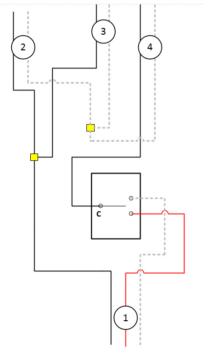
Take a look at this drawing and verify that the connections are accurate. This looks pretty straightforward.
1 Like
@Bry Dude so are you like the batman of this community? You’re a hero! This is exactly the wiring of the 4 sets coming in, yes, really appreciate you taking the time to make this. The only discrepancy (which I’m not sure is even relevant) is that technically the black wire was on the same side of the switch as the red, and the white was on the side that you have the black listed (look at my first pics you’ll see what I mean, again not sure if it matters, the switch did say ‘Common’ Where the black wire attaches from set 4, so if this diagram noting the C is the normal way to note common and the left/right of the switch doesn’t matter then we’re all set). Other than that note, this wiring is exactly correct. Based on this, what would you recommend I try wiring to the red inovelli dimmer? I’ll go try right now…
@Bry technically it looks like this
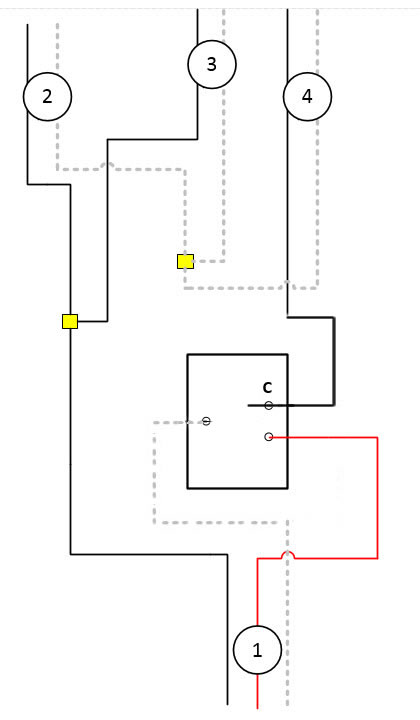
Thanks for the kind words. The #4 connection is ok as either of us drew it. The important part is the fact that the black conductor is connected to the black screw of the switch.
I’m reasonably sure that you have both the line and load in this box. To confirm, use a meter to test between the black bundle wire nutted together and the white bundle wire nutted together. You should have a constant 120V. Test with the switch in both positions.
If that is correct, then the light is on #4. Following on that, the way this circuit works is that the constant hot is sent to the other switch (which you don’t have or can’t find) via the black conductor of the 3-wire. There the switched hot is returned to this switch via the red and grey travelers and out the common terminal to the light.
Are you sure you don’t have another switch? The reason I’m asking is that if the other switch has in fact been removed, it makes sense just to wire this as a 2-way.
Post back when you’ve been able to verify the constant hot across the 2 bundles with the switch in both positions. Also advise if wiring as a 2-way i.e. just this switch is ok.
1 Like
@Bry Just making sure you saw this? (other switch you’re looking for maybe…?)
Thanks again. How do I send you a beer.
@Bry shares the same wall as the original switch in question, put wiring notes on comment # 32
I saw that before but didn’t you say that those switches don’t control the light(s) we’re working on? The real question is if there is another switch anywhere that controls these lights.
1 Like