ok just making sure you saw that. Yes that’s correct, no other switches attached to the original switch that I can see or find, I could pull out the light fixture if that would help?
I’m not entirely sure I’m using the multimeter right, but I get readings/values out of both the white and black wires in both positions.
Ok, if you are absolutely sure that there isn’t any longer a 2nd switch we can wire this as a 2-way. You are going to need a length of a black conductor. If you don’t have any Romex you are going to have to go get some.
If you are going to go buy some, is this circuit on a 15 amp or 20 amp breaker?
You will also need 3 small wire nuts to cap off single conductors.
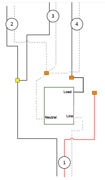
@thx - I think it’s close, but looking at it again, you’ll need to ensure you tie neutral from 2, 3, and 4 together to include the Inovelli switch. Edit the drawing to combine the orange and yellow WHT wires together. If @bry is correct that light is Set 4, you’ll send up the neutral to the light as well on white. You’ll need to test from set 1 if white or red is constant hot. That one will be your line (maybe it’s confirmed above and I missed it).
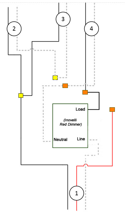
@thx - Correct. I’d wait until @bry confirms, but this should be it. Looks like Set 2 is your line from load center, set 3 is to the next switch/outlet, set 4 is your light (load) and set 1 is a switch that is hiding under drywall or somewhere. If the BLK from set 4 is long enough, you won’t need the pigtail, but I believe that is why you’re looking at buying some 14/2; to extend the blk wire.
I believe #4 is going to the light. Remove the #4 black from the switch and test between it and the neutral (white) bundle to make sure you do not have 120V across the #4.
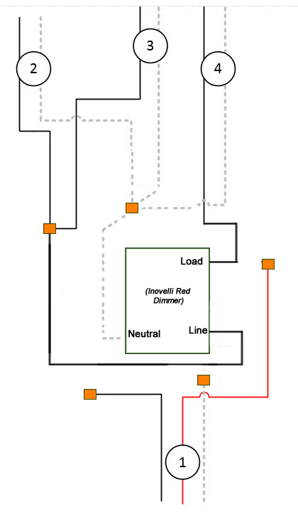
My thought was to make this a 2-way, since you don’t believe the other switch exists. To do that we take the #1 wire completely out of the equation:
Remove all three conductors from the #1 wire and cap them off. (Leave the bare ground connected as it currently is.)
Pigtail a black conductor from the #2/#3 black bundle to the Line of the Inovelli.
Pigtail a white conductor from the #2/#3/#4 white bundle to the Neutral of the Inovelli.
#4 Black to the Load of the Inovelli.
Use the bare ground from the old switch the the green Ground on the Inovelli.
BTW, your most recent drawing that @harjms agreed looks ok looks ok to me too. The way I suggested takes the 3-way variable out of it. To my thinking, the simpler the better. There are 2 three-way settings for the dimmer, and since we don’t know what they’ve done on the other end why even go there.
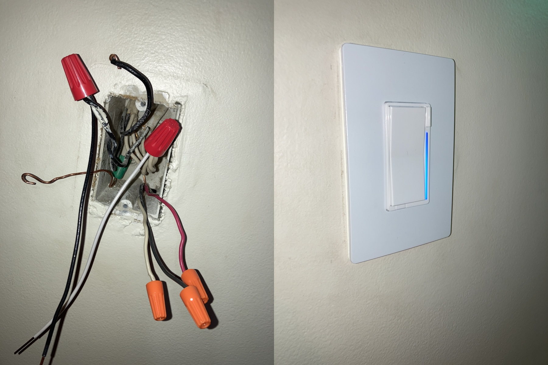
Another tip. Since you are pulling a black conductor from Romex to make your black pigtail, do yourself a favor pull a white one too. The white pigtail from Inovelli is sometimes a bit short. Plus the stripped long end is tinned, which makes it harder to wrap around an existing bundle and sometimes requires you to go up one wire nut size. (Sorry Eric!)
You have nothing to be sorry about, what you said is spot on. The tinning is a nice touch, but a slightly longer and/or solid core wire would be nicer. It’s not as bad in larger wire bundles, but can be slightly frustrating at times.
I think it’s fine as-is. You removed the hot feed to it, so the other end shouldn’t be energized. Actually safer now that you’ve converted to a 2-way. Since you don’t know where the other end is, it’s possible that you had an illegal covered box. You still may have a covered box, but it no longer violates code as it cannot be energized.
Thanks for the help guys. I’m guessing it’s at the bottom of the stairs somewhere capped . There is a breaker label that says ‘basement recapt’, could that have something to do with this maybe? Maybe that’s the other end of it? I can switch that off and see if anything happens to the other switches. Unless there is a way to detect it in the drywall or something for used/unused wire without cutting it open I’ll follow @Bry 's analysis and just let it be.
Thanks again. One quick parting question while I have you though, regarding that switch that shares the same wall, which has the two black wires coming into the bottom of the switch (comment 33), you think I’m good to do the same thing with those I did with the blacks in the switch we just finished? Cap them and add a black extension going to the line?