TL,DR; I have to turn my unpowered circuit off before I can turn it on.
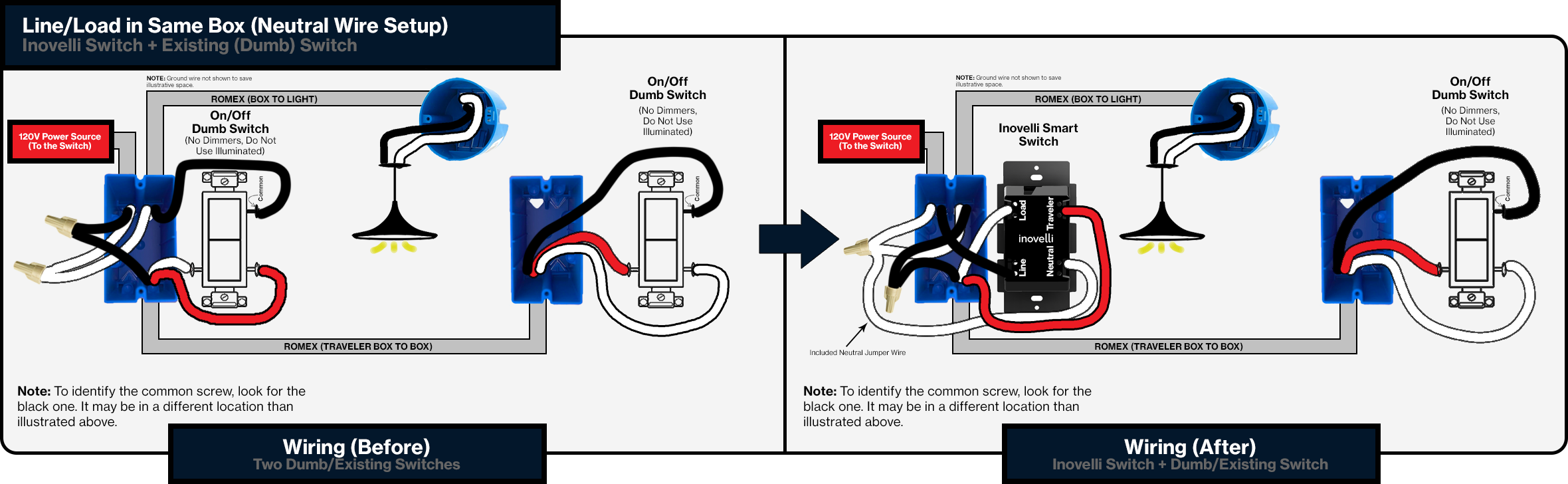
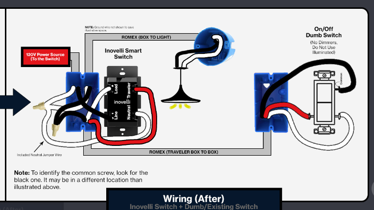
Here’s the story. Most of the 3-way circuits in my house are Line/Load in Separate boxes (Neutral Wire Setup) but I came across one that was Line/Load in Same Box (Neutral Wire Setup). No problem, just follow the diagrams and everything will be fine. Unfortunately, I could not get the switch to behave in the way that one would expect.
If the light is turned on by the dumb switch, I click down on the paddle to turn it off. If I want to turn it on, I click up on the paddle (nothing happens) and then down on the paddle (it turns on). Then to turn it off, I need to click down paddle (nothing happens) up paddle (nothing happens) down paddle (it turns off). Other times the light comes right back on as soon as I turn it off at the smart switch.
I thought this was a problem with my wiring so I used a meter to test each wire end to end at every point. I know exactly which wires go without question now. I rewired it and have the same problem. Ok. I reset the switch. Issue persists. I program step 6. Issue persists. I’m getting frustrated here but I have one more switch in the 10-pack that I haven’t touched yet. I think, maybe the switch is bad and I pull the switch and put in a brand new LZW30-SN. Mother of pearl, the issue persists.
I figure, okay I’ve had enough for one day. I’ll post in the community on Monday. In the mean time, I’ll take this first switch and put it in a single pole circuit that I had intended for the last switch from the 10 pack. I tested my wires to make sure I had Line correct and installed it. Would you believe I have the exact same symptoms on a single pole?
So now, here I am. This has got to be a known issue, right? How can I have the same problem with two switches if it’s not.
All kidding aside, I lost you with the 2-way description. You said the symptoms were the same, but he problem with the 3-way related to the dumb switch, which there isn’t one with a 2-way.
Hi @bryan, could you provide a wiring diagram for the circuit, or pictures of both switches pulled out of the box? Let’s focus on the 3-Way issue first - maybe post the 2-Way issue in a separate question with pictures/wiring diagram.
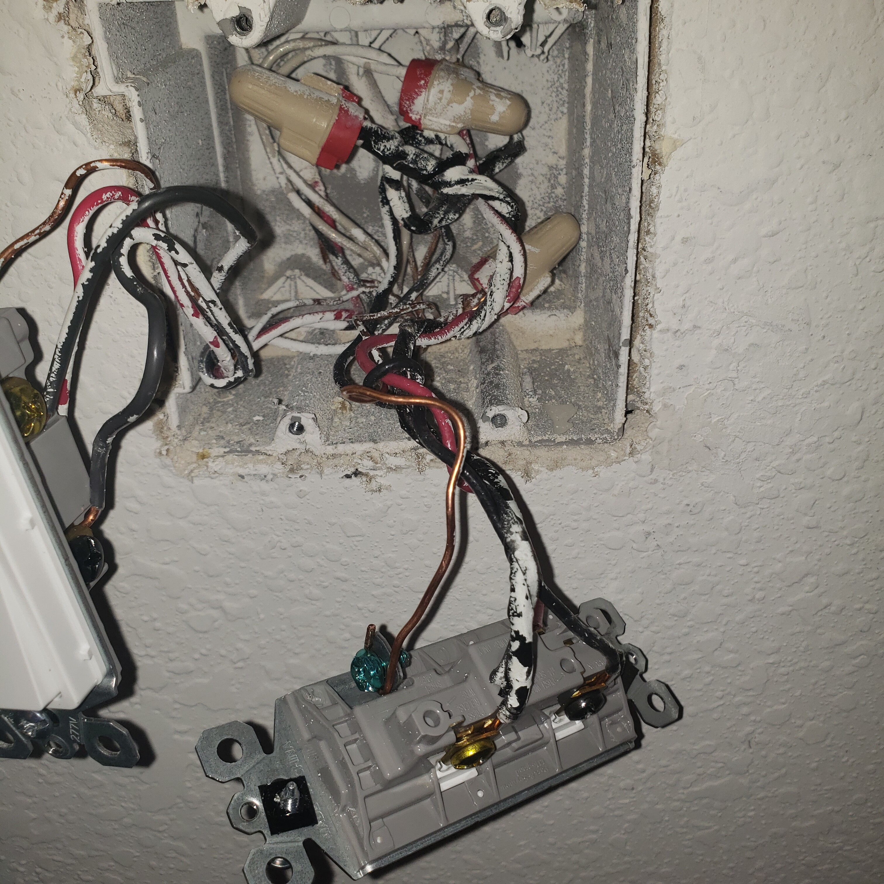
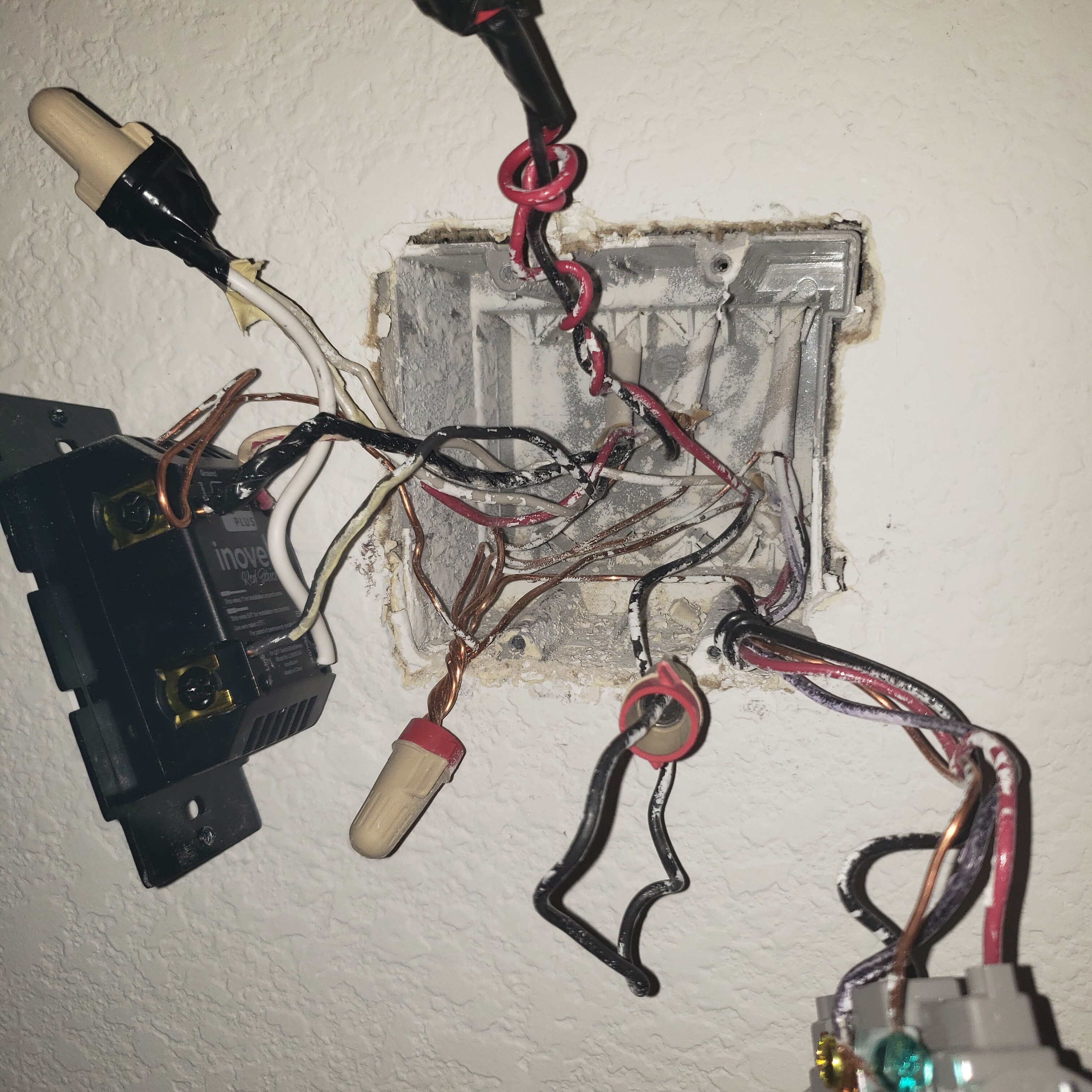
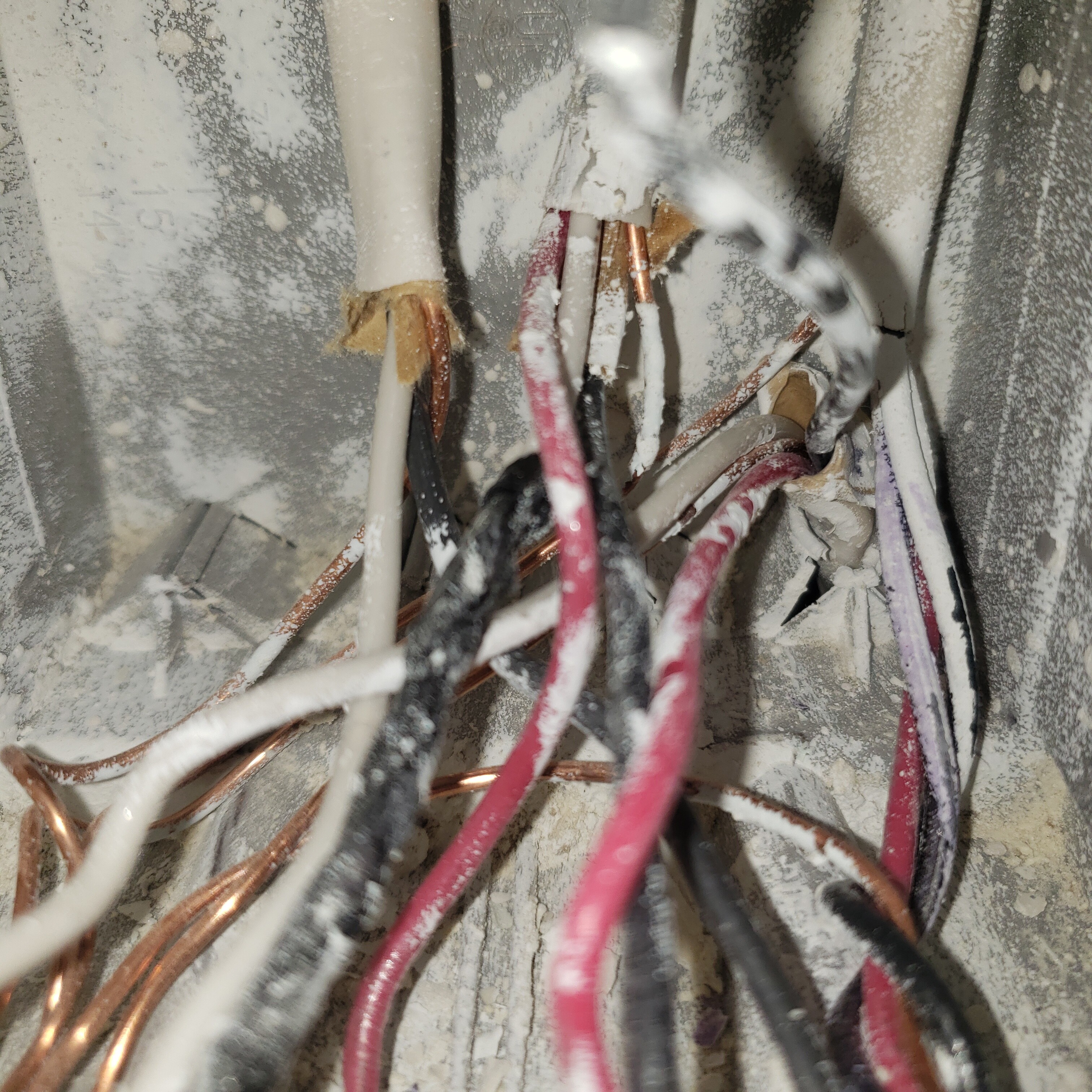
For the Junction box on the smart switch the wire in the first position on top (from the right) goes to power (2 wire). The wire in the second position on top goes to the dumb switch (3 wire, wrapped, red, black). The “tape wrapped” wire in both boxes is the same. The wire in the third position on top is an unrelated circuit. The wire on the bottom left goes to the light. The light is using the red and white wires. The black is unused (terminated on both ends).
This is based on a quick look at your dumb switch only.
That’s not a Line/Load in the same box, if you really have a Line at the Inovelli box. If it was, you’d had the Line and Load in the Inovelli box, and in the dumb switch box, you’d have all three conductors from the 3-wire connected to the dumb switch (which you don’t).
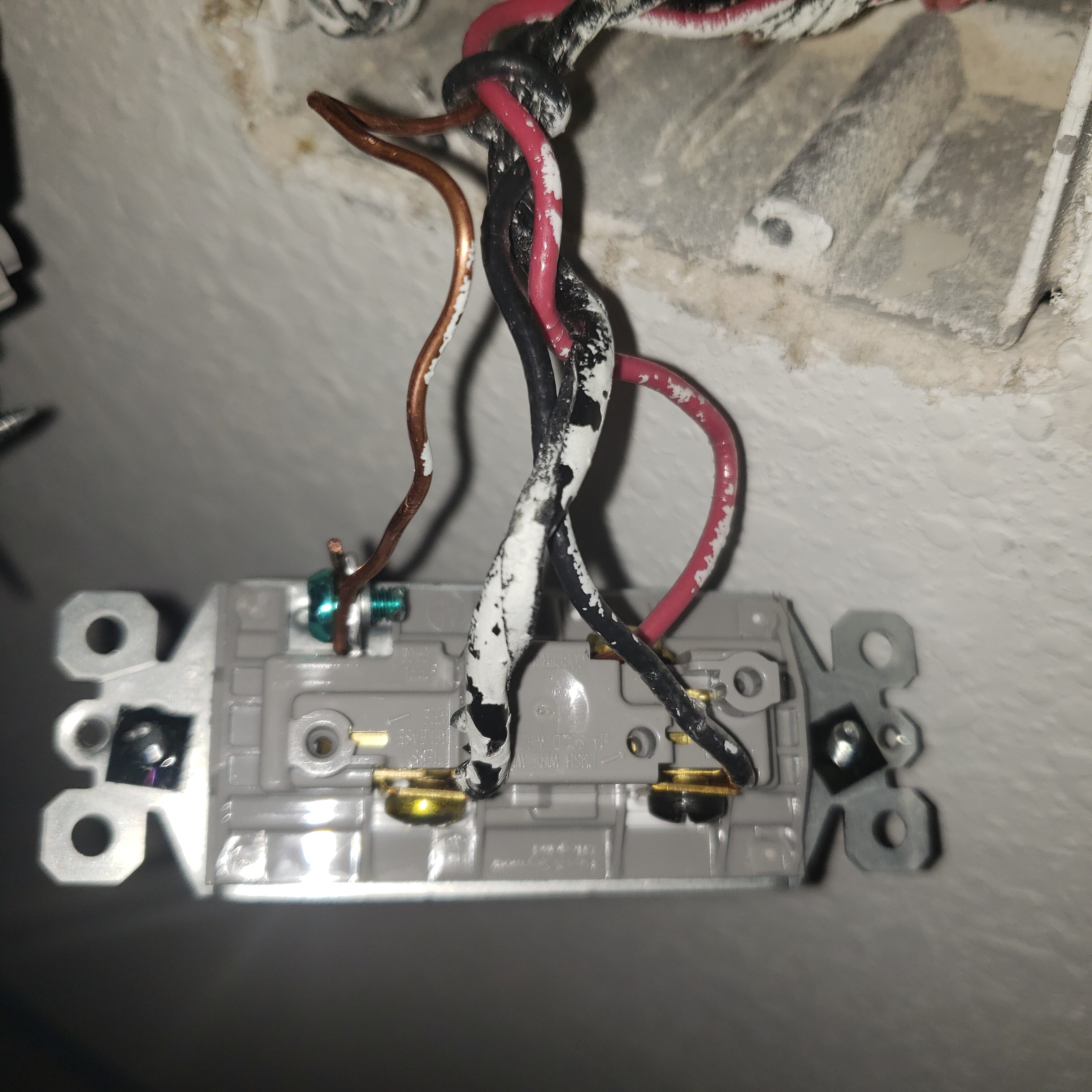
On you dumb switch I see 2 blacks and a red. I didn’t look at your Inovelli box pic, but looking at the dumb switch wiring, I see a black conductor wrapped around others. This can vary among electricians, but it’s commonly used to show the common, which in this case might be the Load. It’s a bit tough to see in the picture, but I think you’ll find that it’s connected to the black terminal on the switch.
Refer back to the last one I helped you with. Was that coiled black the Load? If it was, probably the same here.
In any event, as before find the 2-wire Romex in each box and test between the black and the white to find your line. The other 2-wire without voltage will be the Load.
Ok, so I looked at the Inovelli box. The resolution on your pics leaves something to be desired. When you take them, if you could do whatever you did the last time 2nd time around, those were much better.
I thought I saw 2 black conductors going to the Inovelli, but it appears that a white conductor is wrapped in black tape. In the Inovelli box, are the conductors going to the Line, Load and Traveler all from the same 3-wire Romex? Hard to tell for sure.
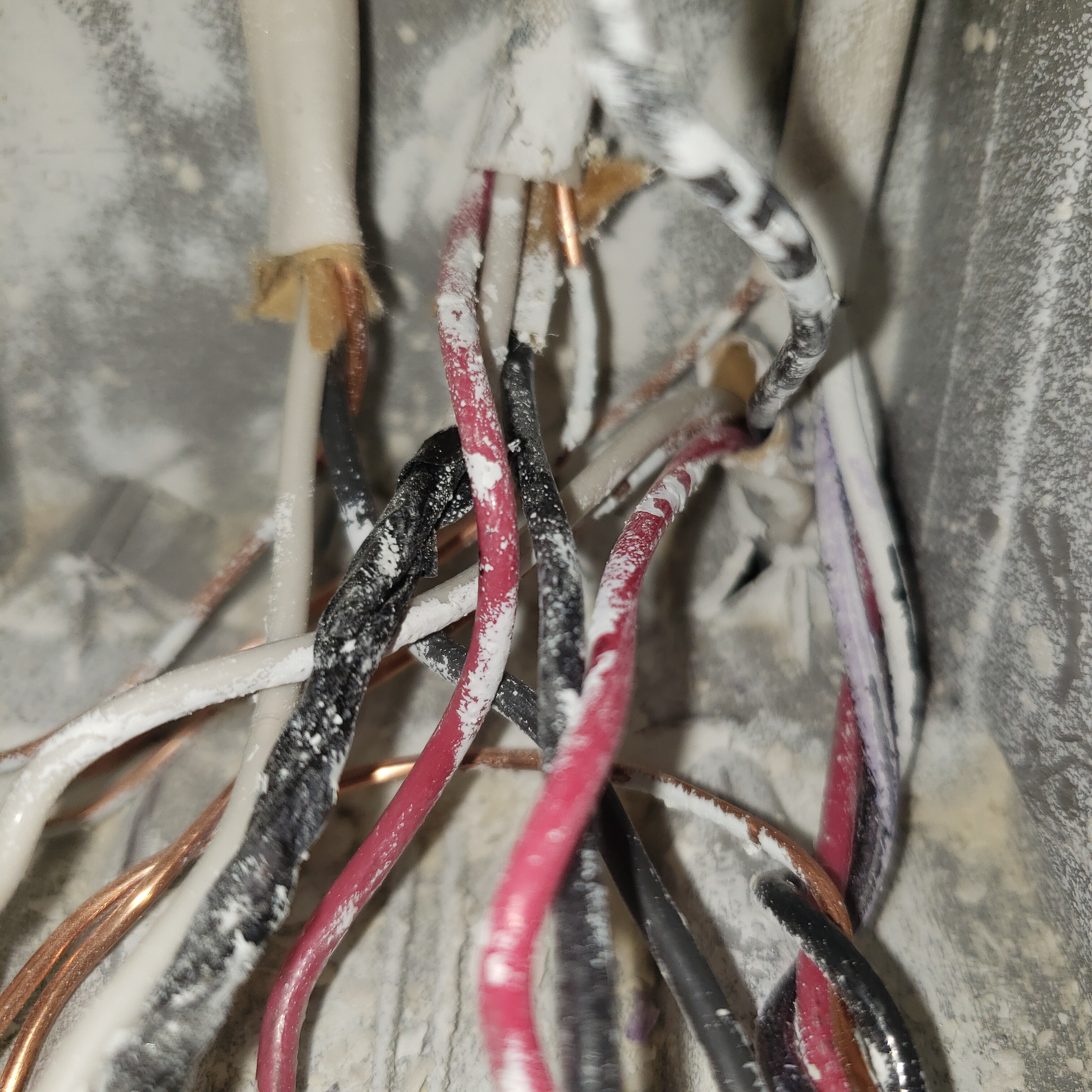
Look a little more closely at the dumb switch (it’s why I included so many pictures). The Black, Red, and Wrapped wires are all coming in on the same Romex.
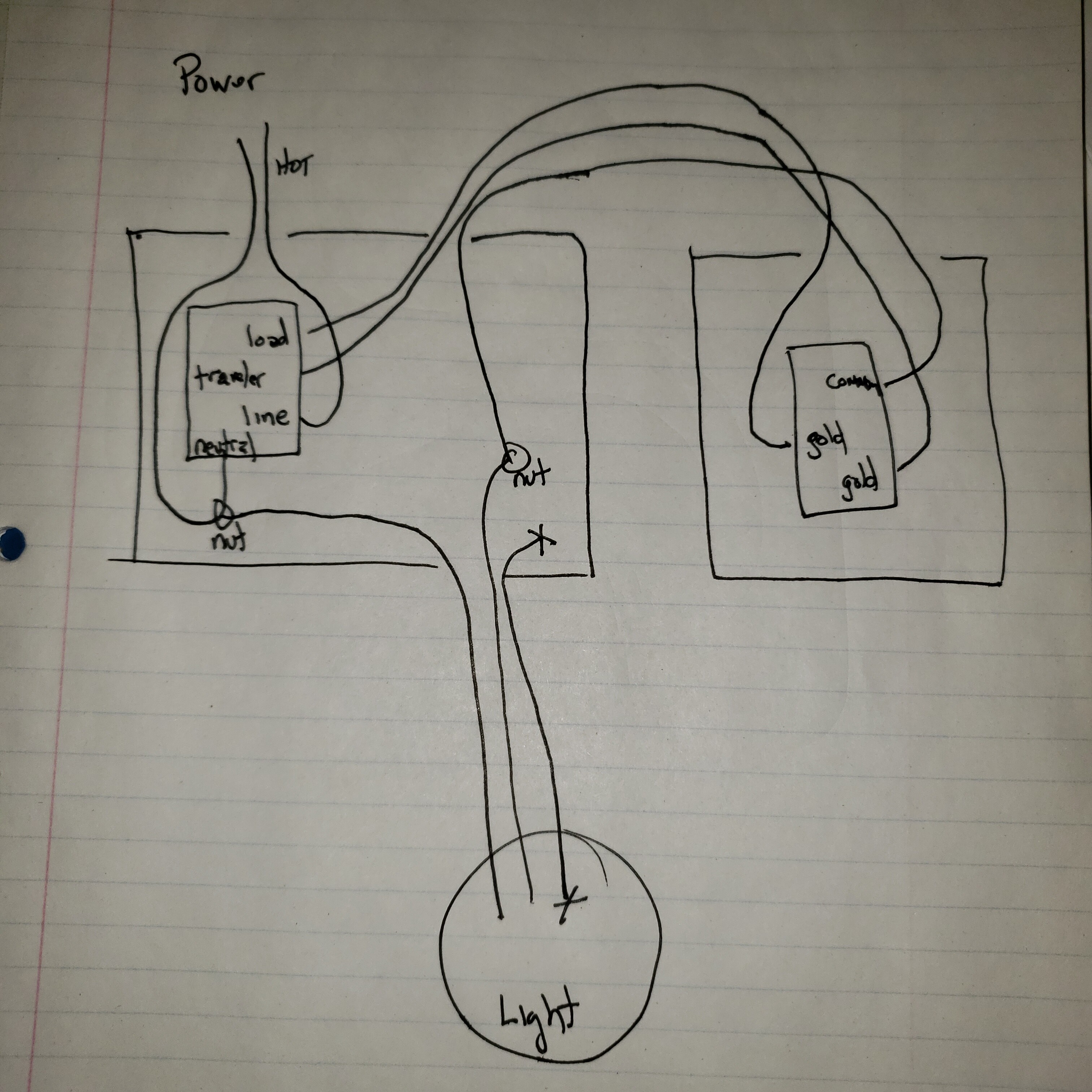
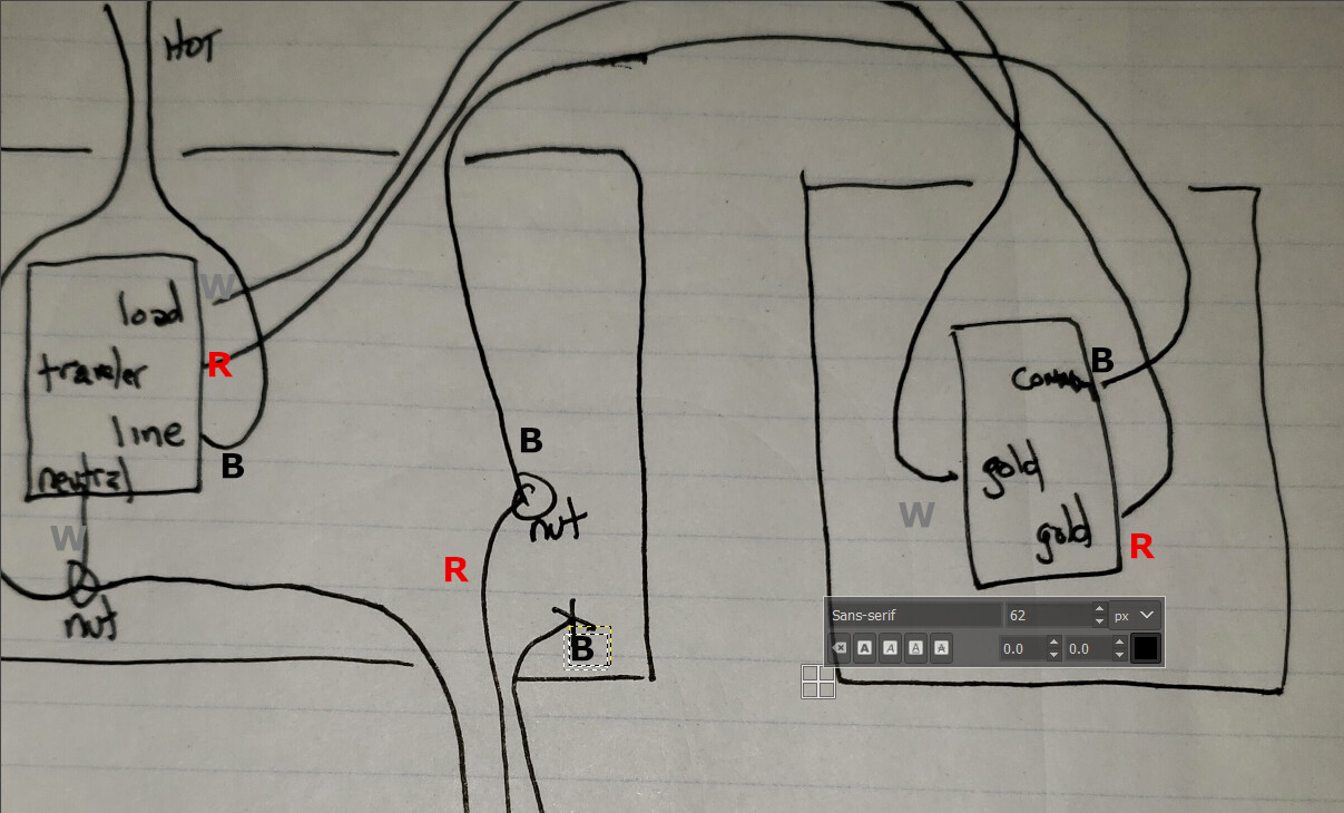
I’ll draw it out like this:
In the first box:
Power romex (2 wire in 1st position)
Black wire connected to LINE on Inovelli.
White wire connected to neutral gang with wire nut.
Traveler romex (3 wire in 2nd position)
Wrapped wire is connected to LOAD on Inovelli
Red is connected to the TRAVELLER on the Inovelli
Black is connected to the red wire in the romex going to the light.
Light Romex (3 wire in bottom position)
Red is connected to the Black wire in the romex going to the dumb switch
White is connected to the neutral gang with a wire nut
Neutral gang is connected to the Neutral on the switch
In the fixture box:
Red is connected to the black wire in the fixture with a wire nut
White is connected to the white wire in the fixture with a wire nut
Black is terminated with a wire nut.
In the dumb switch box
3 wire coming in from other box
Black is connected to common
Wrapped is connected to gold screw
Red is connected to gold screw.
I know my Black on the power romex is hot in the smart box. I tested it with a meter. I tested every other wire in the circuit and there is no other hot. I also tested continuity on each wire individually to confirm both sides of each. The only thing I see in here that is different than the diagram is that for whatever reason the red wire to the fixture is used instead of the black, and the white wire to the dumb switch in the diagram is actually a black wire wrapped in tape at both ends.
I think you’re going to have to draw this out. From your description, you have a line and load in the Inovelli box. It sounds like from your last post that in addition to the 2-wire Line, you have two 3-wires involved.
I am presuming that one 3-wire is going from the Inovelli box to the light and the other 3-wire is going from the Inovelli box to the dumb switch box. Is that what you’re thinking.
If that is correct, which of the 3-wres as you described them (Traveler or Light) is going directly to the dumb switch. I thought that was what you called the Traveler Romex, but say that one conductor is going to the light?
If you can draw this out it will help make sense of what you have.
I neglected to mention the terminated black wire in the 3 wire to the light in the box with the Inovelli in my previous post. Perhaps that created some confusion.
I don’t think that diagram is going to be helpful, unfortunately. I don’t think it’s accurate. You have Romex, so all three conductors in the 3-wire at the dumb switch box have to go to the same place (the other switch box, right?). Yet in your drawing you have 2 conductors going to the switch box and one going to the light. That can’t happen with Romex. I see some other things, such as where the Load is connected to the Inovelli but no sense in discussing that further as I don’t really think your diagram matches your configuration.
At this point I don’t know what to suggest, as it’s tough to get detail from your pics.
I drew some direct lines that were intended to declutter the schematic. The wire from the dumb switch box that is drawn directly to the light is actually bridged in the other box with a wire nut.
This drawing illustrates that (as well as the couble terminated black wire in the romex to the light).
I double checked each of my connections just now. These are accurate.
Ok, way better on the 2nd drawing. The drawing matches the Inovelli and from what I can tell the connections to the switch are correct. I labeled the wire colors in your drawing and matched them up.
Yes, to answer your question, it can certainly be something else. I just like to insure the wiring is correct first.
The switch doesn’t have a parameter to set the wiring type like the dimmer does; it auto-detects. My suspicion is that it doesn’t always auto-detect properly.
One thing to try is to factory reset the switch and then re-add it.
Parameter 13 was added in firmware 1.17, and devices shipped in the past couple of months are shipping with 1.20. The default setting is to auto-detect, but let’s see what @bryan knows about his settings changes.
That’s right, but you’re referring to the parameter for special load types like a T-8, which also might fix issue though. But I was referring to the dimmer’s parameter 21 where you specify the wiring type, i.e. 2-way, 3-way toggle, 3-way dumb switch. The switch autodetects that, supposedly, but that could also be the issue if the autodetection isn’t working properly.
I hadn’t added the switches to Home Assistant yet so I did all of them last night.
One thing to try is to factory reset the switch and then re-add it.
I have done that and now the behavior seems different. When the dumb switch is in the A position the Inovelli works as expected. When the dumb switch is in the B position, Pushing up on the paddle of the Inovelli does not change the lights at all. The blue light will blink once and I can hear the relay click once, but the lights don’t come on. Pushing down on the paddle does not produce any sounds or visual indicators.
Also, what bulb(s) is this connected to? It is a single fixture with 3 TCP 9w LED lamps.
Also, what firmware is the Inovelli on? firmware is 1.21