I have two smart mmwave switches set up to control a light it is fed from the downstairs switch and the light can be turned on currently via upstairs switch but the downstairs switch is not doing anything it shows via the status light the switch is turning on and off but no response with the light.
The wiring is basically the light switch downstairs has a line that has constant 120 power and 1 black load wire that feeds the upstairs switch and a red wire that according to the diagram is not necessary.
right now downstairs is wired as the line and load are both in the “Line” holes and neutral and ground.
Upstairs is a line that feeds it (Comming from the downstairs switch) a load that feeds the light and red (which instructions say is unnecessary)
Upstairs is wired as Line (from downstairs) in line and load in load neutral in neutral and ground in ground.
Additional:
i can control the light via hubitat if i controll the upstairs switch but nothing if i attempt to turn on or off the downstairs switch.
in hubitat i have switch mode as “on/off”
Aux switch type is “Smart Aux Switch”
Smart Bulb mode is “Dissabled”
i see a “Bind Initiator” and “Bind Target” no clue if i need to do something with these.
I sort of understood your topology description. Here is how this should be wired, presuming my understanding of your description is accurate.
I think your line originates at the bottom box. The load going to the light is in the upstairs box.
If that is correct, then this is the wiring. It may be what you have, but it was a bit difficult to tell from your description (at least to me ).
In the bottom box, wire the incoming hot and neutral to the Line and Neutral terminals on the switch. Wire the black and white from the 3-wire to the 2nd set of Line and Neutral terminals. Bundle the grounds and pigtail a bare copper to the switch’s Ground. Cap off the red from the 3-wire.
In the upstairs box, connect the black and white from the incoming 3-wire to the Line and Neutral terminals on the switch. Connect the black from the 2-wire going to the light to the Load terminal. Connect the white from the 2-wire going to the light to the 2nd Neutral terminal hole. Bundle the grounds and pigtail to the switch. Cap off the red from the 3-wire.
I think this is more or less what you have, but just confirming.
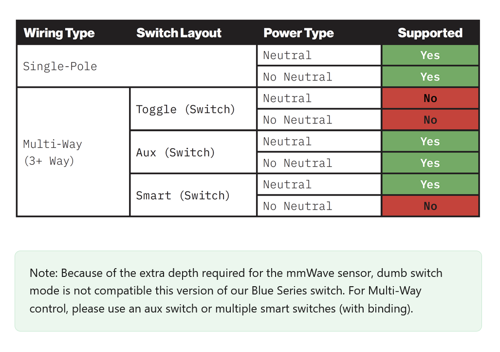
Your upstairs switch is now the primary switch. It should be configured as a 2-way, with no Aux switch.
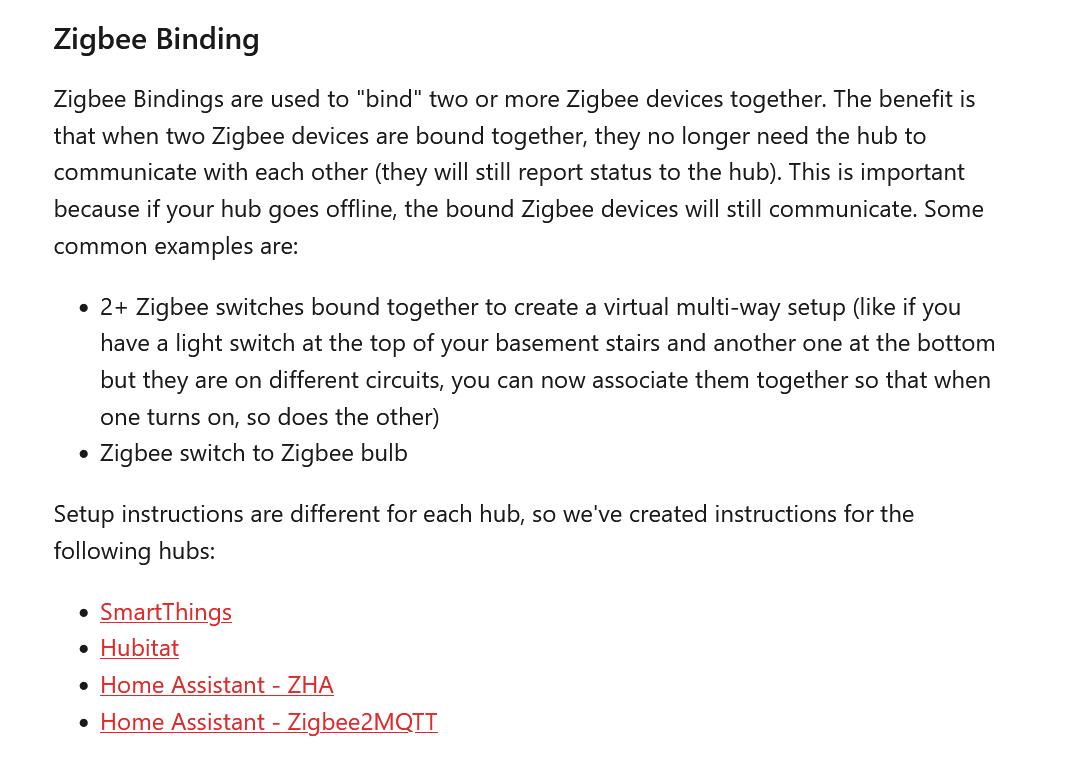
To control the light from both switches, you’ll need to use binding to bind the two switches together to keep them in sync and to allow the bottom switch to communicate with the top switch. I’ll leave it to a Hubitat user to explain the binding part.
Presuming the load are dumb bulbs, since SBM is not enabled.
I believe that the wiring that you stated is the same as what i have. I guess i just need to figure out how to do the Binding portion there is nothing about it in the directions that i have seen. I have set the upstairs to “No Aux” and the downstairs to “Smart Aux” and still no control of upstairs light from downstairs switch.
Unfortunately, I don’t have any experience binding switches - I’ve only bound a lighting Group (2 Hue bulbs) to my mmW, and i used the binding option in the mmW driver to do that.
In hopes that this guidance is still current/applicable, I’d perhaps start with this help article:
The downstairs one doesn’t really matter what you have it set to. It’s simply a scene controller that will be bound. It doesn’t have a load. There should not be anything connected to the load or traveler terminals on that switch.
I’m sure a Hubitat user that binds will jump in shortly. In the meantime, take a look at this:
Those instructions are what i needed someone needs to add them to the installation instructions an outlet that can’t control the light is pretty useless
Not sure which installation instructions you referred to, but in addition to Zigbee bindings being a commonly understood concept, the mmWave manual, the product page and the wiring instructions all discuss binding.
I am not here to argue whether it could have been easier or better explained maybe i am not the demographic that this switch was meant for. Maybe i should have known about binding switches together shame on me. I still feel like saying that somewhere in the hubitat system you will have to do something potentially related to binding is a far cry from something like “For the child switch to function you will need to set up {Insert term or link} and link the switches.” Instead there is a QR code on almost every page if i scan them all and finally figure it out how many people won’t and will instead return them? Thats all i am saying isn’t that what everyone wants, bring in people that are on the fence to hope for wider adoption? But thanks for helping me out and i hope that if anyone else has the issue i had they will be able to come here and see all the super helpful links (well a couple are helpful but to be honest some are not meant to be helpful you just wanted to show that i don’t know what i am doing) But like i said thanks for getting me where i needed to go and hopefully this will help someone else.