I have a weird 3 way situation I haven’t seen up here. I have 2 Red Dimmers, V2, (LSW31-SNs) and a GE 46199 Aux switch as an add-on if need be. I’ll be using Hubitat once they are wired up, so I would also appreciate what settings I have to do there.
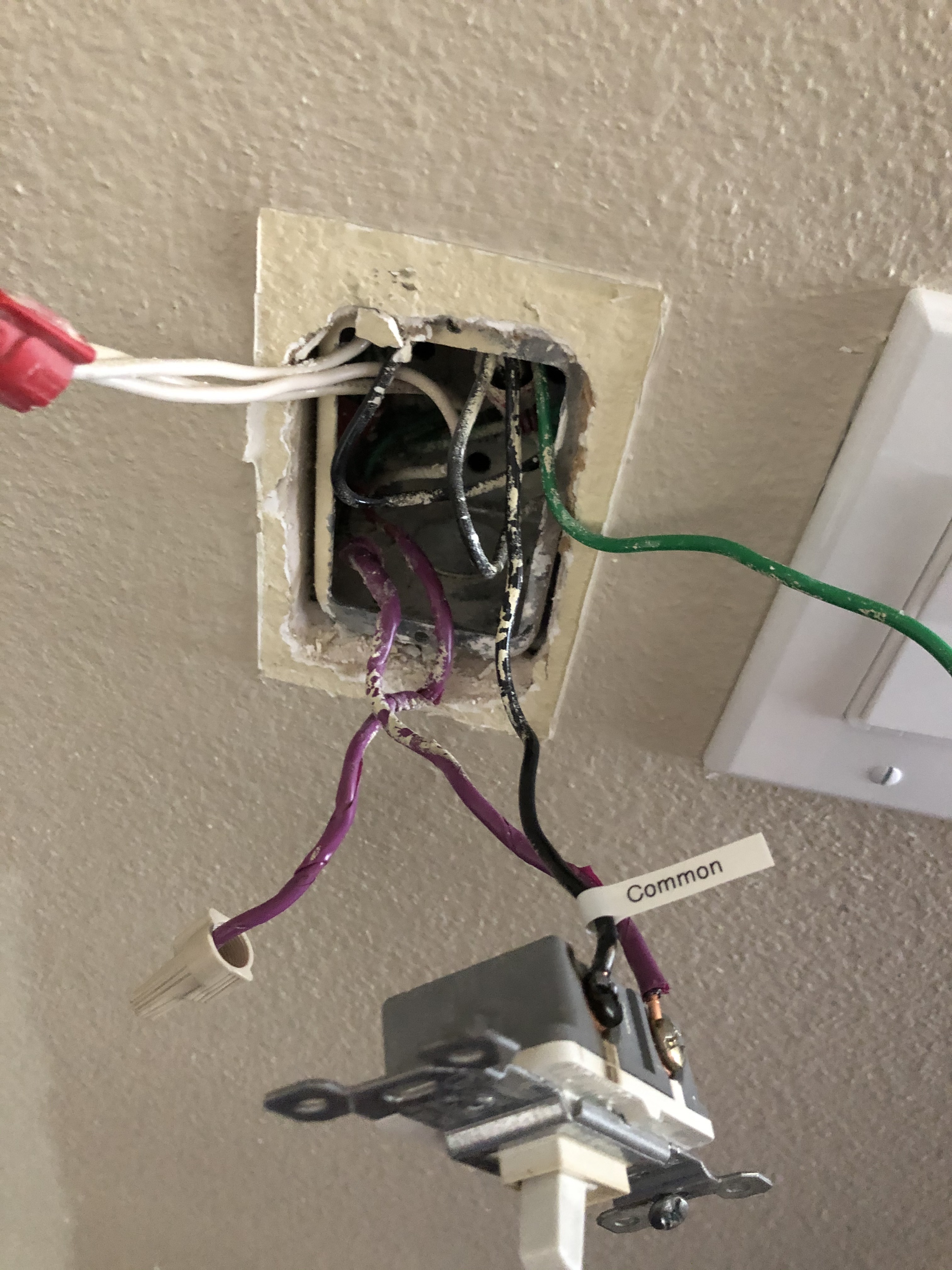
Box 1 has a neutral, a common for power and 2 travelers.
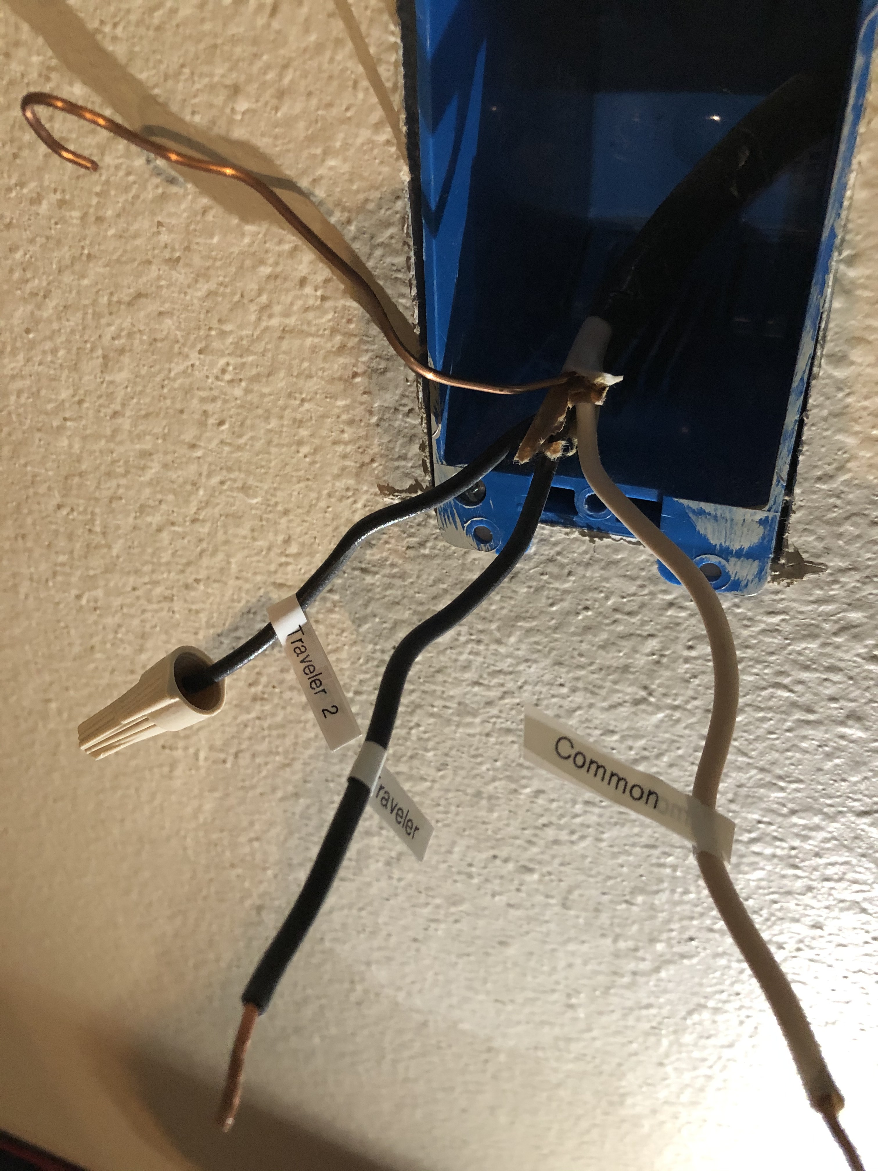
Box 2 has a common, which my electrician is convinced is going to the light and 2 travelers.
I’ve included photos below, but please note the pictures were taken while we were taking the switches on and off trying to figure out how to wire it and does not reflect either the original situation or any set up I tried.
Box 1.
Note: One traveler (purple wire) was capped off while we were working on it as are the neutrals. The neutrals were not being used in the original set up.
I can tell you what you probably have, but think you should consult with your electrician as well. These are much more difficult to diagnose when you don’t have pictures of the working configuration and when you have individual conductors instead of Romex.
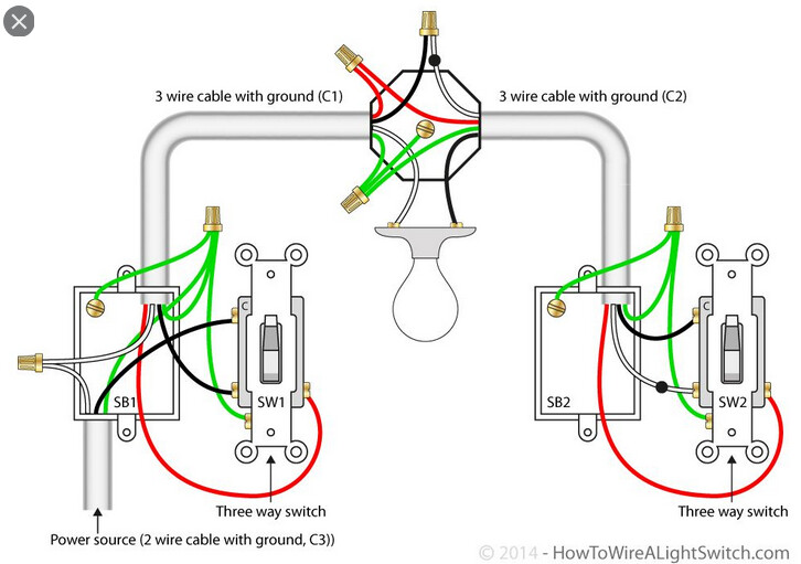
That looks like a power to box 1 then going through the light and to the box 2. Is this controlling a single light and can you get at it to look in the box? Since you have conductors going through the light, the key to confirm this will be to look at the connections in the box.
Take a look at this and see if this makes sense. The reason i believe the light box is in the middle is based upon only 3 conductors in Box 2 and the fact that the probable travelers are one color in one box and another color in the other. If this is the case, it’s nothing weird or anything, it’s just another way of wiring a switch leg. If you concur that this is what you have, post back as Inovelli has a published diagram for this.
I had the electrician hook it back up like it used to be for now, so I can open the switch plates and provide pictures if need be. I don’t know how to see the wiring in the can. The electrician didn’t really want to come back until I know how to wire this up, so I’m in a bit of a catch 22 there.
I only have 1 Red Dimmer and the Aux switch at the moment as I had 2 bad Red Dimmers out of 20 I got and Inovelli is sending me a new replacement. If the solution involves an RD and an Aux switch maybe I could try the solution myself. So please direct me to that solution.
BTW, we know it was a jury rig as the other light switches in my condo are all in metal boxes with conduit and neutral wires, while you see one is in a blue plastic box without a neutral wire. Plus the other two 3 ways in my condo are a “standard” line in 1 box and load in the other.
I found an Inovelli 3 way non-neutral solution at the link below (it was the very last one on that page), but it doesn’t look like your diagram. In your diagram there is power to both switches from the light. In the Inovelli diagram they only show powere to one light from the switch.
I do have one other question about using the Aux switch. I saw somewhere that I’m supposed to put it into non-neutral mode. If that is so, please tell me how to do that too.
You and I must have different definitions of jury rigging, It’s not uncommon to add on to electrical circuits to make it more convenient. The plastic box you see is an “old work” box. It’s designed to be put in after the sheetrock is up. So whoever added that box after the house was built did it correctly.
Also, in a 3-way switch leg, you’re not going always going to have a neutral in both boxes, and in what I think is your wiring configuration, you shouldn’t have a neutral in the far box. So if the diagram is correct, there is nothing wrong with your wiring. It wired in a very common configuration.
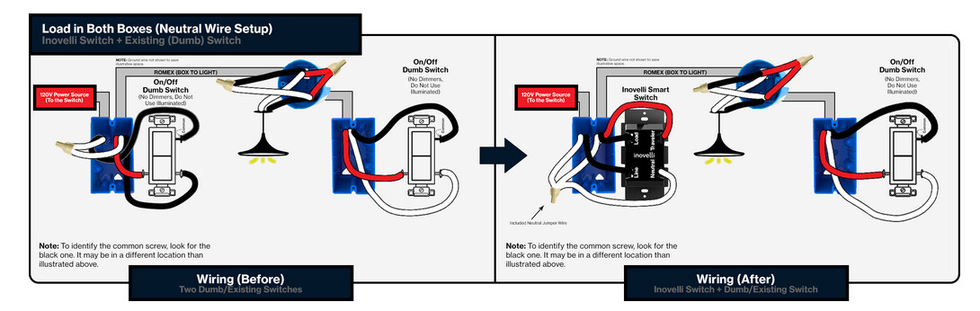
You don’t want a non-neutral configuration as you have a neutral in Box 1, where the Inovelli will go, presuming the diagram I suggested is correct. And you don’t have a power in the 2nd box. You have power that is switched via the travelers, but that’s it. That is what is expected.
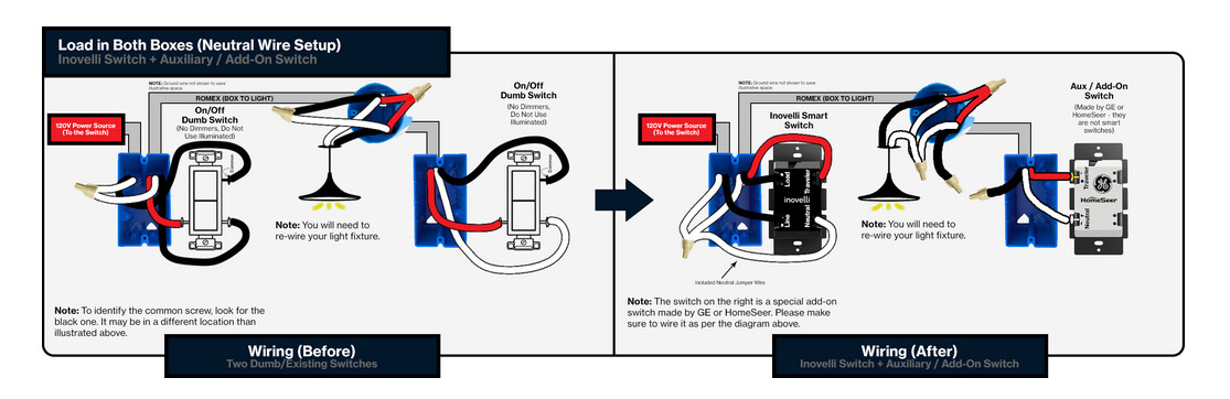
The Inovelli diagram below is the proper one based on the diagram I suggested. Bear in mind that I can’t say for sure it’s proper without testing. I encourage you to continue to seek your electrician’s help. Given the diagram, he ought to quickly be able to confirm if it’s correct. We can work with him just as easily.
Please don’t take this wrong, but you may not have as much electrical knowledge as you think you do. There’s nothing wrong with that, but you have to know when to seek qualified help. No one wants to see you get hurt, start blowing up Inovelli switches because they’re installed incorrectly, etc.
Thanks for taking all the time to respond! I was calling it “jury rigged” as that was what the electrician called it. By that we meant it was added later as a afterthought. Considering how every single other box is vs. this one, and how the other 3 ways were wired, it certainly seems like this wasn’t planned for originally and then was added later.
Also, I think I have virtually zero electrical knowledge. I’m just trying to follow the diagrams. I was presuming I would be using a non-neutral wire setup as my electrician was telling me there was no neutral wire in one of the boxes.
From the diagrams I see that the fixture needs to be re-wired so I won’t be trying to just add the switches myself.
Since I’ll be using an Aux switch do I have to program it in any special way before I install it? Assuming your diagrams are correct and it gets wired properly does the Inovelli and/or Aug switch need to be programmed in Hubitat afterwards? (In fact, do I even do an Inclusion of the Aux Switch? (I didn’t see any instructions on how to put the Aux switch into pairing mode, so I’m guessing I don’t).
Got it. I’m guessing just part of a remodel to add another switch. More than likely, it was easier to run the 3-wire to the new box from the light box instead of the other switch. That’s a perfectly normal way of doing it.
Your electrician is correct. There is no neutral in Box 2, but you don’t need one in Box 2. If my diagram is correct, there is one in Box 1 and that is the only place you need one.
I agree that you shouldn’t try to add the switches yourself. But if those switches were working properly, there may not be any need to re-wire the light box. Your electrician won’t know until he takes a look.
There is a setting that specifies you are using an Aux switch. See @harjms post above. He is on Hubitat as well. I’m on SmartThings, so I’m not familiar with Hubitat stuff.
Once you get it wired up and included to the Hub, I’ll help ya get parameters setup. Aux switch is a dumb device (even though they’re expensive) so it doesn’t require any inclusion.
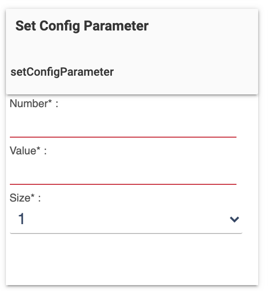
I am using Hubitat. I know how do an association using the Z Wave Association Tool and I’ve set the ramp and dimming rates as there are specific entries for those inside a device in Hubitat, but I’m not sure how to set multiple other parameters. I see there is a place to set one other parameter in Hubitat (see the screen shot below). Is that used to set multiple parameters?
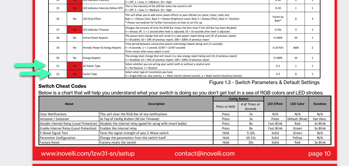
I see those are in Hubitat, but I have no idea what parameters 21 and 22 are/were as the chart printed in the LZW31-SN instructions only goes up to 20. Which is 21 and which is 22?
Thanks for posting this! I’m going to share with the manufacturer as it looks like they printed an older version of the instructions. Ugh…
Can you let me know if there was a wiring insert in there at least? I can check myself tomorrow, but I didn’t want to open up a fresh 10pk to double check.
BTW, I had only glanced at the insert before and looked at them again to answer your question. I hadn’t changed the Switch Type Configuration (Step 6 of the insert) for my 3 ways as they have Red dimmers on both ends. I’m not having any issues that I can see because of that, and the choices (in Hubitat, at least) are 0 for a single setup, 1 for multiple switches with a dumb switch and 2 for multiple switches with an Aux switch. So, should I have changed 22 in Hubitat for the Switch Type? If so, what value would I put in when using Red dimmers on both sides?
Well you’ve done more than 90% of people lol. Usually it goes straight in the trash!
So, the switches weren’t meant to have two smart switches at both ends. It’s honestly something we didn’t even think people would want as typically people use an aux switch or a dumb switch. Admittedly, it was overlooked in the initial design process so from a hardware side of things, it’s not officially supported.
But, as I’m sure you saw in the wiring diagrams, all the secondary smart switch needs is a constant line and neutral in order to function and then from there you can Associate them together.
So, to answer your question, you would just leave it as a single-pole setup and then Associate them together once your wiring is confirmed. In other words, no need to configure the switches if you have two smart switches on the same multi-switch circuit.
I’ve been looking at smart switches for years, and years and years. (My family knows, correctly, that I love researching stuff as much, if not more, then actually buying stuff. Plus I am extremely picky and particular to an insane degree.) I wanted all my switches to be one brand so they all looked and worked alike. I kept reading about how the Lutron Caseta was supposed to be #1 (and maybe they were before you guys came along) but didn’t buy them, or any other brand, for several reasons:
As to the Caseta, I didn’t like the physical buttons as I thought it would be too easy to push the wrong one, especially at night.
Again, as to the Caseta, they didn’t have a favorites button, except the Pico remote
They didn’t support multi-tap (scenes)
They didn’t have a configurable LED notification system. You guys have color, brightness and notifications, which I hadn’t even dreamed of.
For 3 ways they had the Pico remote, but that is battery operated and I wanted something powered.
Lutron, and everyone else I looked at didn’t have an LED on both ends of the the 3 way to show the dimming level.
I wanted a 1 gang fan and light switch with dimmers for both.
Plus you really need to get the Lutron hub and each switch is very expensive - about $60 each (that is what I just saw looking them up on Amazon).
Inovelli is the first (and as far as I know) only company that makes a line of switches that satisfies all of those criteria! (And I grew up in Detroit, the 3-1-3, and have a sister-in-law living in Kalamazoo.)
It is #6, having the dimming level LED on both switches, that is most relevant here. I don’t know about others, but that is why I got 2 Red Dimmers for both sides of my 3 ways, which you guys do with the Group 3 association. (BTW, you need to update your Wiki to include the Group 3 association going the other way on your Wiki page. Right now it doesn’t mention Group 3 at all.
)
The only thing else that would be nice for you to make is maybe a remote, ala the Pico remote - but I think that should be a fairly low priority as most people will probably use Alexa/Google to talk to the devices and/or use a dashboard ala Hubitat or the Alexa or Google app.

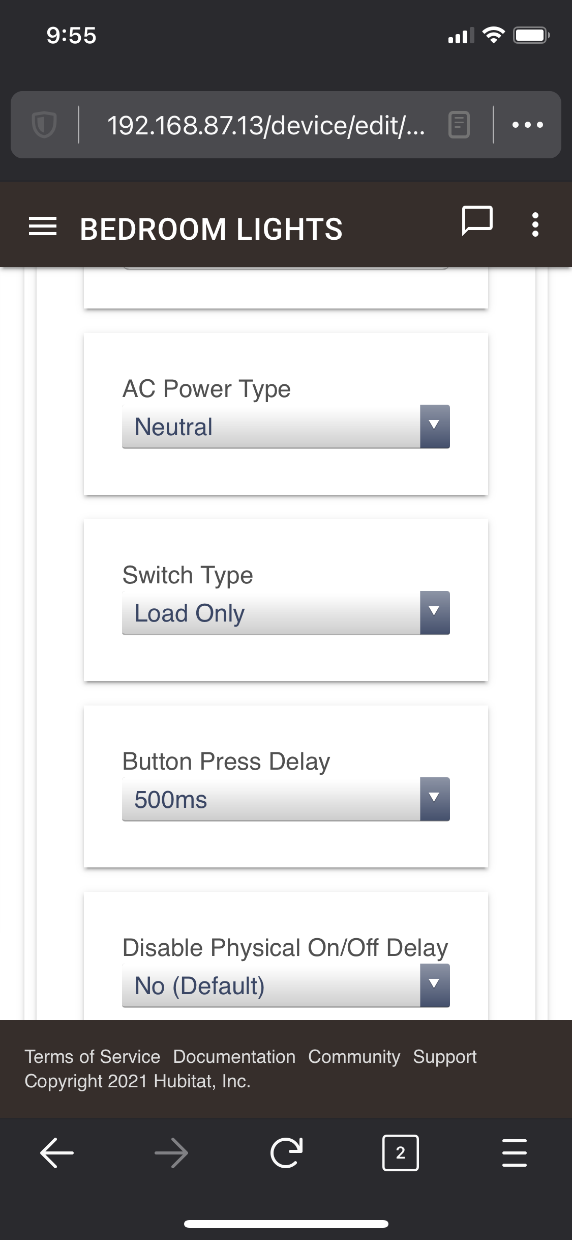

 and looked at them again to answer your question. I hadn’t changed the Switch Type Configuration (Step 6 of the insert) for my 3 ways as they have Red dimmers on both ends. I’m not having any issues that I can see because of that, and the choices (in Hubitat, at least) are 0 for a single setup, 1 for multiple switches with a dumb switch and 2 for multiple switches with an Aux switch. So, should I have changed 22 in Hubitat for the Switch Type? If so, what value would I put in when using Red dimmers on both sides?