Trouble wiring Z-Wave Gen2 On/Off Switch in 3-Way Scenerio

@Bry pretty sure you drew the same diagram I put up LOL glad someone else is seeing it too.

There’s going to be some re-wiring required, but I think I’ve got it figured out. I can picture it in my head just trying to put it down into words.

I’m sorry, I certainly didn’t mean to steal your thunder. I recall you saying power was coming from the light and I agreed. Didn’t fully get my head around the logic until just now.

I’m not understanding about the re-wiring. My diagram is what is there now and at least in my mind, that ought to work.

The switch can’t go into box #2 because you need a neutral to use a dumb switch in a 3way. So the white wire that feeds power to box #2 needs to be unhooked from the bundle and repurposed.

I follow that, but if you re-purpose the white then you’re just left with travelers in box #2. There was discussion about using an Aux. Doesn’t that do away with the requirement for the neutral in box #2 then?

Or in the alternative, you could re-wire to not “send” the hot. That just makes my head hurt again.

I THINK this should work. Again, I’ve never used a dumb switch with a smart switch before.

SB1
-Remove white wire A from BWW bundle and add a jumper (preferably black) from the bundle to the LINE of the inovelli switch.
-Connect white wire A with red wire B using a marette. White wire A will be connected to the common terminal in SB2 and red wire B should be connected to the light. This essentially gives the common terminal in SB2 a direct connection to the light.
-Red wire A would go into TRAVELER on inovelli switch. This should already be connected to traveler in SB2.
-Black wire A woud go into LOAD on inovelli switch. This should already be connected to the other traveler terminal in SB2.
-Add a jumper (preferably white) from the neutral bundle to NEUTRAL on the inovelli switch

Bry is absolutely correct, the common on the LeGrand switches are deceptive. You can verify the common by loosening the black screw and see which wire becomes loose.

So I looked at was going on and realized that the initial assumptions on A & B were not correct. The Key was the wiring of the 2 3-Way switches. I thought instead of burying the 3-Way function in this post I would create a new one… see Anatomy of a 3-Way Switch

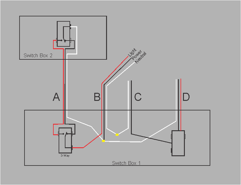
This is what I believe you have:

To wire your smart Dimmer in the A1 position you simply:

A - black - dimmer Load
A - Red - dimmer traveler
These above two could be reversed with no effect.

B - Black - dimmer “Line”
B - white - dimmer Neutral

IMPORTANT:

  1. You should get some bare #14 and run wires from the bare wire marret to the ground(green) wire of the dimmer. The electrician should have run the bare to every switch and receptacle green wire. The lazy ba__ard should loose their licence. And as Bry said their color choices are WRONG for just the reason you are having, by picking seemingly random colors for the different wire functions it makes any changes much more difficult.

  2. Tell your girlfriend (nicely) that this is more of a learning experience than just installing a smartswitch :slight_smile:

Let me know how you make out.

John

@JohnRob I got the same conclusion. The only thing I think you’re missing is
A - White connect to
B - Red

The common terminal from switch 2 needs to be fed back up to the light.

@Bry to wire an aux you only need 2 wires. Neutral and traveler. Having never wired a smart/dumb 3way, I only mentioned it because I knew how to wire it right away.

For an aux switch
A - White - add to neutral bundle. Goes into Aux neutral in SB2
A - Red - Inovelli traveler and Aux traveler in SB2
A - Black - cap off on both sides, wouldn’t be used.

B - Red - Inovelli load
B - Black - Inovelli line
B - White - Inovelli neutral

Agreed. I know that works with the GE/Jasco’s, wasn’t sure about others.

Maybe I’m totally missing something, but how can you put the smart switch in box 1 (A)? The dimmer needs a constant hot on the Line (Common) terminal, right? You don’t have that at switch A. There are 2 travelers and the switched leg to the light. The red connected to the Line (Common) on A will only have power part of the time depending on the position of the switch in Box #2.

@Bry there is no hot currently to the existing switch, but there is hot in the box. Let me pull out my trusty MS Paint at the office and I’ll take a crack at modifying the diagram, it may come out looking like my 3 year old drew it though LOL

I understand. I was taking the drawing as the new configuration.

I understand that the hot has to be wired to the common in #! and “removed” from being sent to #2.

Someone with more advanced editing software can clean this up

@MRobi @JohnRob

Agreed. That should do it.

Took us long enough, lol.

Which is how I stated the dimmer should be wired. I must have missed the part about the Aux switch.

@JohnRob the aux switch part was just me saying that’s what I would personally use instead of a dumb switch. OP has no plans of using an aux switch here, but if anybody in the future searches it the info will be here.

You guys rock! I am going to give MRobi’s suggestion a go when I get home tonight! Let’s keep fingers crossed :slight_smile:

I’ll update you how it goes. Thanks again for everyones help! Lol this is just switch #1 of 10 I am putting in. So lets hope the rest go better ahha! I’ve learned a lot on this now so if the rest of them are like this I have a pretty good idea of what to do now.

Glad to know this was a really “weird” setup and not just a regular wiring scenerio.

I’m not sure what you mean by "Line (Common) terminal.

In my diagram the known hot B-Black will go the Dimmer “Line” terminal.

John

Right. Disregard. I mistook your drawing as the implementation, not the current state.

You only get one consult per month, lol.