Blue Series 2-1 Signal / Routing / Performance Issue Troubleshooting Thread

I am in the middle of a remodel and the electrician will be here in a day or two. I’m trying to rework a few switches so that the electrician can install them and I won’t have to pull them out to replace them, since the replacement switches haven’t arrived.

It took me 20 minutes to disassemble and solder 4 switches. In about two hours, I’ve only been able to reassemble one switch. Those aggravating pins will not go in. I’ve tried all kinds of suggestions from here in this thread, but I just can’t get the pins in.

Is there a place we can order new replacement pins? Reusing the existing pins just isn’t working.

I was wondering this too. I have managed to repair 17 switches so far. And I’ve got 20 more to go on my bench.

2 Likes

Thanks Eric. I got my email.

Hey great question regarding the 24’s. It’s a great question and while I’d love to do that, it would add another layer of complexity to the situation, so I think it’s best to do a 1 for 1 swap.

I also don’t have a timeframe right now on when the 24’s will be released.

How long did this take per switch on average?

I’m impressed at your workflow. I’ve soldered some hobby projects before so am not fully a novice but also am not anywhere near a professional. I thought I had fixed two of my switches. However one didn’t power up correctly (I might disassemble it and check if somethign is loose) and the other one shows no improved performance. Its possible I did something wrong with it.

Its a really delicate procedure and reassembly is difficult. I am losing interest in trying to repair them and might only use the official replacements. I was hoping to be able to fix a couple and put them in less critical locations that I wasn’t planning on having a smart switch. The issue is I just have limited free time and having to shut off the breakers and install and test with the family around is tricky especially when the procedure is difficult.

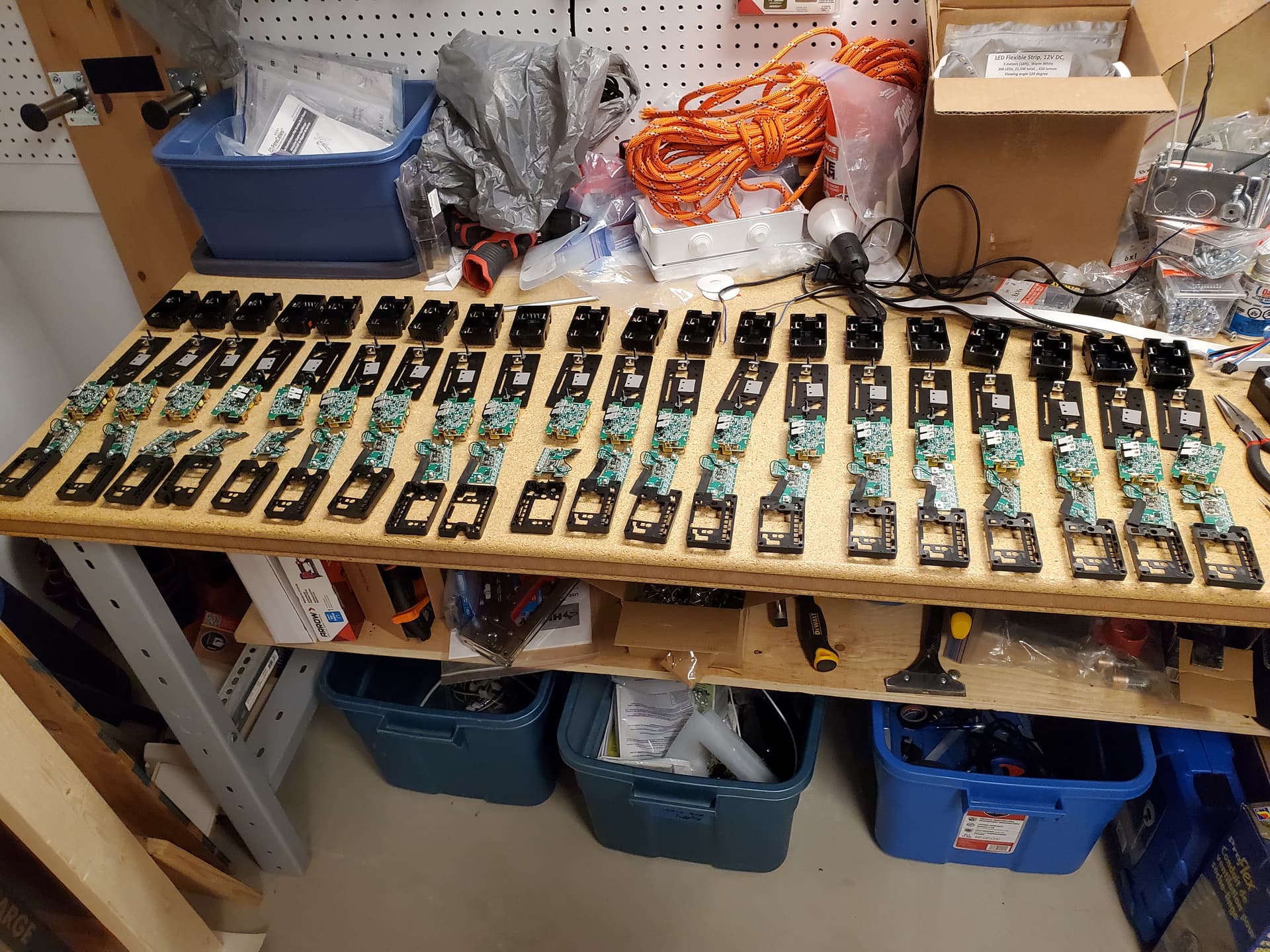
I did the first few one at a time. then like 2. then like 3 then like 6. Now at 17 complete. My final batch I am doing all 20 in parallel. Last night i disassembled 20 switches. Tonight maybe solder 20. And then slowly reassemble in small batches and install the same night.

In all honesty, I am probably 10-15 hours in for 17. I also bought a $50 led magnifier arm for my workbench. I ended up burning out my cheap soldering iron and bought another one. Same price point.

It is critical to separate the pin inner and outer. And then install. It is super finicky. I use needle nose pliers and some straight and curved electronics tweezers. I am using a $8 soldering iron from amazon.

My side hobby right now is building about a dozen WLED controllers with parts off of aliexpress. Historically I have jtaged xbox 360s, Motorola modems, and modded consoles dating back to the original xbox. Built every computer I have owned since about 12 years old.

The biggest tip I got from another forum member dan4. His tip on the separating the pins was game changing.
“”"I hear ya, those pegs are bastards. There is a little bit of a cheat though which works and still prevents paddle squish. Start by putting the zigbee board into its plastic housing and make sure it clicks in place. Then attach the power board to the zigbee board - attach the power board pins but don’t put in the plastic pins yet.

Separate the two plastic pins into two separate pieces - just pull them apart - so that you have one that looks like a thumb tack (the bottom piece) and the outside piece which the “sharp” side of the thumb tack goes through. Keep them separated for now.

Using a small piece of tweezers or coffee free hands, put the thumb tack piece through each plate with the “sharp” side facing up. After each one is in place push the metal plate down so that the pin can’t go anywhere. Once you have both thumb tacks in place put the thermal blanket over the pins.

Then insert the outside part of the plastic pieces into the holes in the metal plate. Put the assembled boards back in their power tray then while looking through the sides to align the pins and then press hard into place until they snap into place (this part is crucial, otherwise you will get a mushy paddle). Oh, and make sure that the antenna isn’t getting smushed.

Screw the rest together and you’re done!

I’ve managed to put them together both ways. The OEM method took me a good hour to get the pins together properly - whereas this way takes me about 5 minutes to disassemble, solder and re-attach. For what it’s worth I’m using a stock tip on the Hakko FX888D - you don’t have to be too accurate from what I can tell, as long as you bridge over to R1 you’re good.“”"

I am not 100% sure I have actually fixed them. As I never actually tested a un-fixed switch. Us canadian’s didn’t get the switches until well after the issue was found and reported on. But I still have 37 replacements coming. So I can always swap if I have issues in the future. A bit of a good thing. I also realized that I ordered 7 too few switches. I’m going to order 5 of the fan switches when they become available.

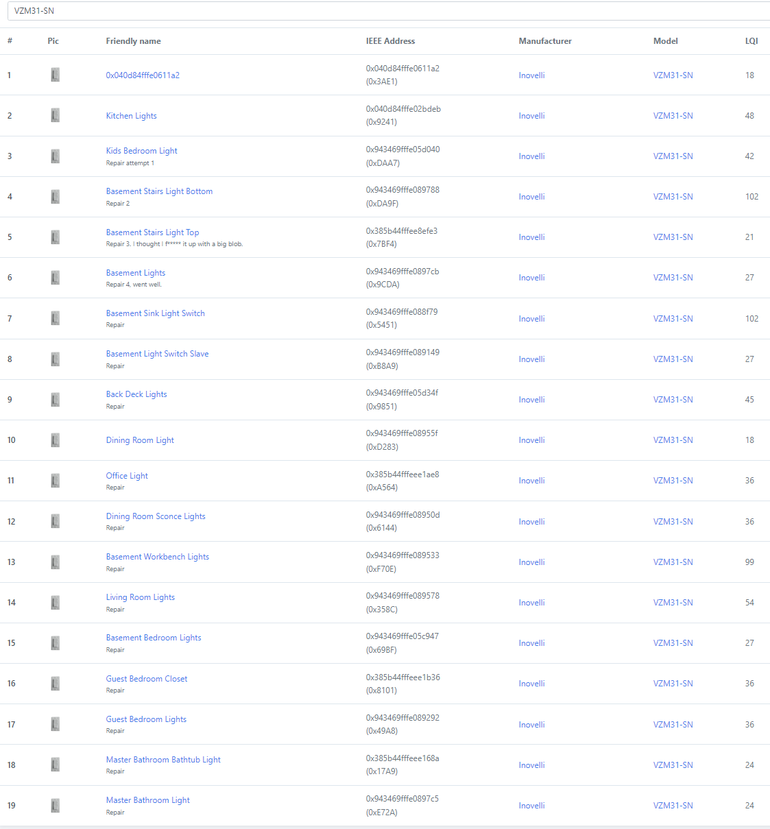
You can see the LQI of my workbench light switch which is immediately next to my home assistant raspberry pi is over 100. Everything else is progressively further out. My house is wood frame. 2 floors and a basement. And only 900sqft per floor. So I wonder if I did properly fix all of them.

Regards,
Aaron

5 Likes

@Eric_Inovelli, Sorry to be a pain, but I just wanted to let you know that I still haven’t seen that email come through on my end. Thanks.

Same here, no email seen at this end @Eric_Inovelli

2 Likes

@Eric_Inovelli and @Courtney_Inovelli ,

I never got a reply back on how you wanted me to proceed with switches ordered from your Canadian supplier (Aartech), but I’ve submitted the form using their order number, and attached PDF copies of the order and delivery receipts as uploaded files along with the other requested information. Hope that will be sufficient.

37 Repaired and 1 of the 37 is now 5V modded.

Initial 10-15 hours for 17.
The last 20 done in parallel took only 7 hours.
And about another hour to 5V mod one.

1 Like

I would recommend that the pins for the MOSFET heatsinks be installed on the MOSFET side, same as the OEM method. The thermal performance is reduced by installing the pin from the heatsink side. The wide flange of the pin is meant to provide pressure across the TO-220 package transistor and reduce the thermal impedance between the transistor and the heatsink with the silpad acting as thermally conductive voltage isolator between the two. Installing the pin from the heatsink side and try to pull the MOSFET to the Heatsink by just the little ball on the end will have insufficient force on the package for good heat transfer. This could lead to thermal destruction of the MOSFETs.

Oh shoot I’m so late to the party. Just submitted my application for 5 switches.

Did not receive an email- was my form submission received/processed?

Just curious for the folks that have done the 90% hotfix for these switches. I’m seeing great connectivity to my zigbee routers (main controller and a few hue devices), but the connections between switches still show up red/weak in my ZHA visualization in HA.

Functionally, everything seems to work well and any automations or events are triggering quickly and as expected, so it really hasn’t bothered me, but was curious if that is what everyone else is seeing too.

1 Like

Did you do the hotfix or just using the defective switches as is?

Did the Hotfix. Took them all apart, shorted the pads and reinstalled them where they were.

I did not exclude and re-include, which may be worth doing now that I think about it.

1 Like

Finally had to give in and fill out the form. While all of my switches are in the batches identified as bad, I actually had no issues connecting them to my Hubitat. Fast forward to today and I’m on my 5th or 6th instance of the zigbee network going offline. Hue motion sensors, which have been reliable for years at this point, are giving me the red dot of doom frequently. Only new addition to the mesh has been blues in the affected MAC address ranges, so they’re the only culprit that I can point to at this juncture.

The bad Blues are almost certainly the offender behind your ZB mesh issues.

If you factory reset them and leave them unpaired, they function perfectly fine as a dumb switch or dimmer (you can program that via the paddle) – that’s what I’m doing as I wait for my replacements.

1 Like

Probably what I’ll be resorting to as well while I wait.

1 Like