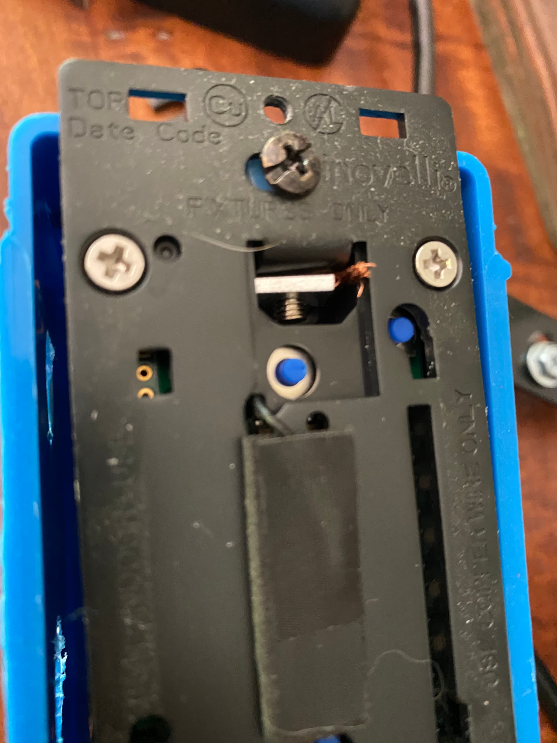
It’s just the frontside of the ground screw, so unless you have line tied to ground and/or a bad circuit breaker, it should be fine.
As a visual reference:
It’s just the frontside of the ground screw, so unless you have line tied to ground and/or a bad circuit breaker, it should be fine.
As a visual reference:
One of the things I like about other switches (non-smart) is they give you a depth gauge on the switch for the press-fit holes. Gives me a good idea of how far to strip back.
Noting that ANY tooling change requires significant cost though… no matter how small.
I believe there is a strip example on the back of these. Hmmm. Mine is temporarily in a box for testing so not a huge deal. I only noticed it after removing faceplate for another issue.
Nice, must be a production unit thing as my beta unit I’m pretty sure didn’t have one.
Doesn’t help for typical ground, which doesn’t have sheathing ![]()
Recommend not penetrating it so deeply then.
The scenario I am talking about is this.
I think setting the default level local param to 100 will fix your issue
Still playing with settings but successfully got my Switch set up in Smart Switch mode and bound to 10x smart bulbs and 1 other Tuya/Moes Knob. They seem to all play well so far. I did get an error when the switch paired though:
2022-10-26 18:52:31Failed to configure '0x943469fffe05cee5', attempt 4 (Error: Read 0x943469fffe05cee5/1 haElectricalMeasurement(["acVoltageMultiplier","acVoltageDivisor","acCurrentMultiplier"], {"sendWhen":"immediate","timeout":10000,"disableResponse":false,"disableRecovery":false,"disableDefaultResponse":true,"direction":0,"srcEndpoint":null,"reservedBits":0,"manufacturerCode":null,"transactionSequenceNumber":null,"writeUndiv":false}) failed (Status 'UNSUPPORTED_ATTRIBUTE') at Endpoint.checkStatus (/app/node_modules/zigbee-herdsman/src/controller/model/endpoint.ts:317:28) at Endpoint.read (/app/node_modules/zigbee-herdsman/src/controller/model/endpoint.ts:480:22) at runMicrotasks (<anonymous>) at processTicksAndRejections (node:internal/process/task_queues:96:5) at Object.readEletricalMeasurementMultiplierDivisors (/app/node_modules/zigbee-herdsman-converters/lib/reporting.js:26:5) at Object.configure (/app/node_modules/zigbee-herdsman-converters/devices/inovelli.js:1219:13) at Configure.configure (/app/lib/extension/configure.ts:115:13) at Configure.onMQTTMessage (/app/lib/extension/configure.ts:55:21))
This is with the latest zigbee2mqtt
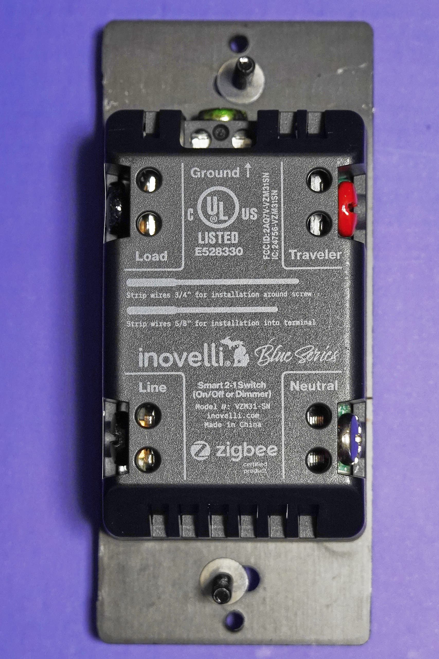
Are there any official photos of the switch? I was looking for one a few weeks ago and didn’t spot any. In case it’s useful to anyone, here’s a pic I took:
In addition to trailing edge dimming that’s been mentioned earlier, it’d be nice if the low end of the dimming range could be made even dimmer (I posted details here)
Recommend the switch type is set to “three way dumb” as the default. I would think most would have them in this configuration and even if not, most things should default to the simplest settings first (like the switch default being on/off). Having to pair it, go into the settings, and change this is too much work just to verify the connections first. Not to mention if these were installed in a new builds where network connections may not be set up yet. Would the master switch work with this as a default even if the aux was on the other end?
I had an issue trying to work out an unrelated three way wiring issue that I had to call an electrician to come fix for me. Everything worked great with 2 three way dumb switches until they replaced one side with the new blue series. We all tried to research and verify the connections…it turned on but had all of us thinking something in the switch wasn’t working correctly. After the electricians left I paired the device and found the setting. A lot of time wasted and they didn’t charge me because they couldn’t get it to work…calling them back to pay anyways because it wasn’t their fault.
FYI You should be able to swap to multi-way dumb by just holding the down paddle, tap config 5x and release the down paddle. LED Bar will flash Violet if it worked, that’s from this link.
This is an interesting thought and I’m back and forth on it – and this is definitely something we debated over from a UI standpoint.
I would say that most configurations are actually single-pole, neutral setups followed by multi-way w/dumb, neutral (and then multi-way w/aux).
However, one could argue that 3-Way Neutral w/Dumb has all the same settings as Single-Pole Neutral and it would indeed save a step of programming and the headaches and shaken fists we get from electricians.
But, on the other hand, what if someone is wiring up an Aux Switch and run into the same issue where they wire it up per the directions and get equally as frustrated that their Aux Switch isn’t working properly?
Because of this, we opted to have the simplest setting of Single-Pole and put a cheat-sheet in the box that has all the quick tap settings. Ironically, it was meant for electricians because that’s one of the biggest complaints we get (that someone hired an electrician and the electrician couldn’t figure out how to get it to work in a 3-Way).
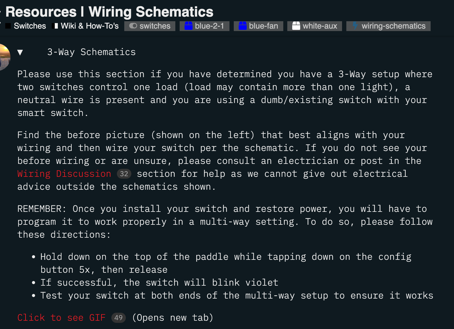
In fact, we also put disclaimers on the wiring schematic site letting people know that they’ll need to program the switch after installation:
–
But I guess I understand from an electricians standpoint that they probably don’t care about reading programming instructions as that’s not their wheelhouse and they probably assume that’s something for the homeowner to do as they’re just there to follow the schematics.
–
One thing that was tossed around was to start offering different SKU’s on the site that were already pre-programmed to work. So, if you know prior you have some single-pole setups, you can order the Single-Pole SKU and if you have a Multi-Way w/Dumb, you can order that, etc.
The problem here is that there is now 5 SKU’s (Single Pole Neutral and Non-Neutral, Multi-Way Neutral (dumb or aux) and Multi-Way Non-Neutral.
Would love to hear what you guys think as this is definitely an ongoing problem that I’d like to solve!
Regarding the eternal desire to control fans/inductive loads, this comment has:
once they are in market, we will start the certification for 1917 so
we can have two UL ratings on them
where 1917 refers to solid state fan control. Is this still in the works? If it happens, is it likely to require a hardware change?
In my specific case I want the 2-1 to be configured in smart bulb mode, with the load being a Shelly 2.5 that’s connected to an exhaust fan. The only time the 2-1 would directly impact power flow is when the air gap tab is pulled to allow me to service the fan or Shelly; otherwise I’ll use switch-generated events to drive automations that reconfigure the Shelly.
Is that something I can expect to work with the current 2-1 switch, even if it’s not certified for that use?
I think SKUs are expensive to maintain, which means cost of switches go up. Simplest thing I can think of is to add a red STOP sticker somewhere on the switch that points to the “setup before use” insert.
Thanks for getting back to me. Yes I understand the predicament. I am assuming this isn’t something that can be determined by the switch itself. Maybe the instruction can be organized in a sequential manner. I noticed the electrician went strait to the wiring section, didn’t see much that was useful to them, and then went online to the schematics. I myself skimmed that section because it seemed to be geared towards a beginner that needs basic terminology explained. While definitely good to have, the intended audience needs to know how to get it correctly hooked up and verified.
My recommendations for the instructions:
First section is compatibility chart found on page 29 (and any welcome/legal stuff). That chart could be the index on where to go in the instruction book. Maybe add a “not sure” line to the chart that directs you to the info found on pages 21-27 that breaks down everything to the basics for the beginners with additional warnings about electrocution and possible damage of the switch if hooked up wrong.
The other lines in the chart give you the page number for the section with everything an electrician or somewhat knowledgeable DIY’ers would need to get the switch up and running from a wiring perspective (to include the relevant button sequence and color). A contractor would love to just do what they need to do and get out of there…or maybe they can stay on the clock longer, but that’s for them to work out ![]()
The following section is the hub/gateway setup.
The next section is the smart and advanced setup and usage scenarios for inspiration or education on what capabilities these switches have.
And last, the troubleshooting steps to determine possible sources of common problems (e.g., smart switch in 3way only works sometimes, lights flicker when dimmed low, etc) and available online resources.
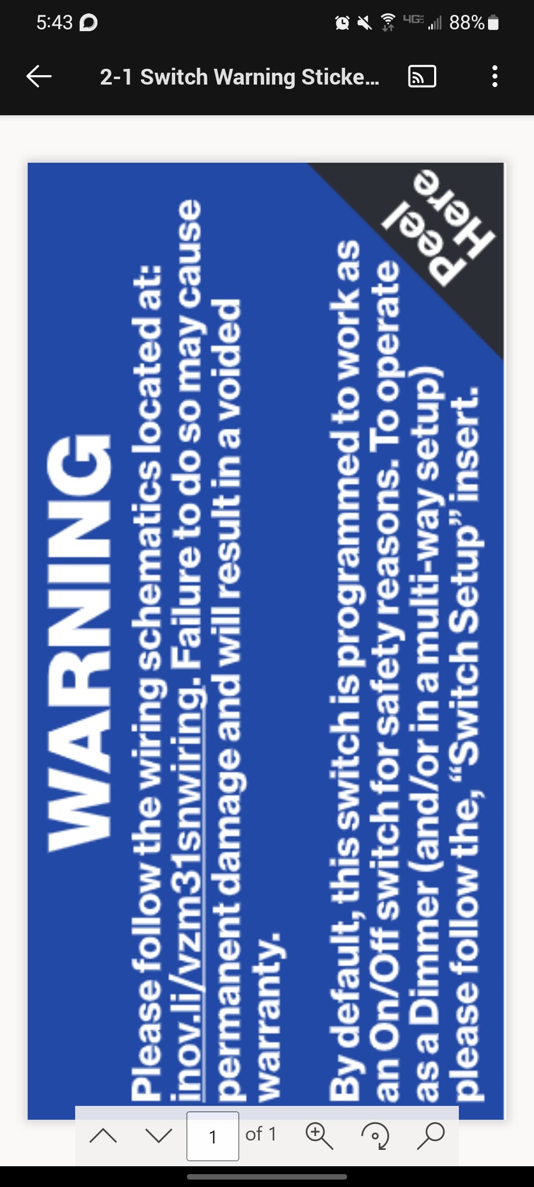
I guess I could modify this one to be a little more clear, but this is what is currently over the line/load and needs to be taken off prior to installation.
The insert talked about on the warning is what I was referencing earlier that talks about programming the switch in a 3-Way.
My guess is that (from my anecdotal experience) electricians are typically used to traditional switches and assume these switches operate in a similar fashion and ignore all the stickers and inserts, which stinks bc we’ve tried all sorts of methods to, “dummy proof” the install.
Everybody is used to warnings on electrical things and ignore it. MOST of the time, these tell me to not eat tide pods or don’t touch hot oil. If you start reading it, you see that it’s talking about wiring and damage and move on.
Maybe separate out the second part which isn’t so much as a warning of damage, but limited functionality you will get if you don’t do anything else.
Put the functionality part as a sticker on the paddle. Can be the paragraph already on the side or something along the lines of “To function as a dimmer and/or three way/multi-way switch, see “Switch Pre-Setup” card in the box” (or just make the sticker the switch config chart itself), or “additional configuration is required to correctly function as a three way/multi-way switch or dimmer, see page xxx of instruction manual or “Switch Pre-Setup” card in the box”.