This post is archived – for the most up-to-date digital manual, please go to: Blue Series Dimmer Switch • Manual | Inovelli Help Center
DISCLAIMER
While we (and our community) try to keep these instructions up to date, it’s often hard due to the many updates to our firmware, Home Assistant app & platform changes, as well as many other factors outside of our control. If any updates/edits need to be made to these instructions, please comment on this thread so we can keep it up-to-date:Wiki - General Feedback/Suggestions Thread
COMMUNITY DRIVEN
Our entire Knowledgde Base (which includes manuals) is community driven. This means that we at Inovelli work together with our amazing community to keep articles up-to-date. We’d love it if you’d contribute in any way you can, be it making edits, submitting how-to’s so others can learn, participating in our innovation projects, or simply commenting on threads. Thank you so much for your support and dedication to really making an impact in the smart home market.Community Knowledge Base
NOTE: All of the pictures can be clicked on to be made larger. Also, if you’re on mobile, you can either click on the pictures or turn your phone side-ways and the pictures will become larger.
Digital Manual Overview
This is the digital manual for the Blue Series Smart 2-1 Switch (On/Off or Dimmer).
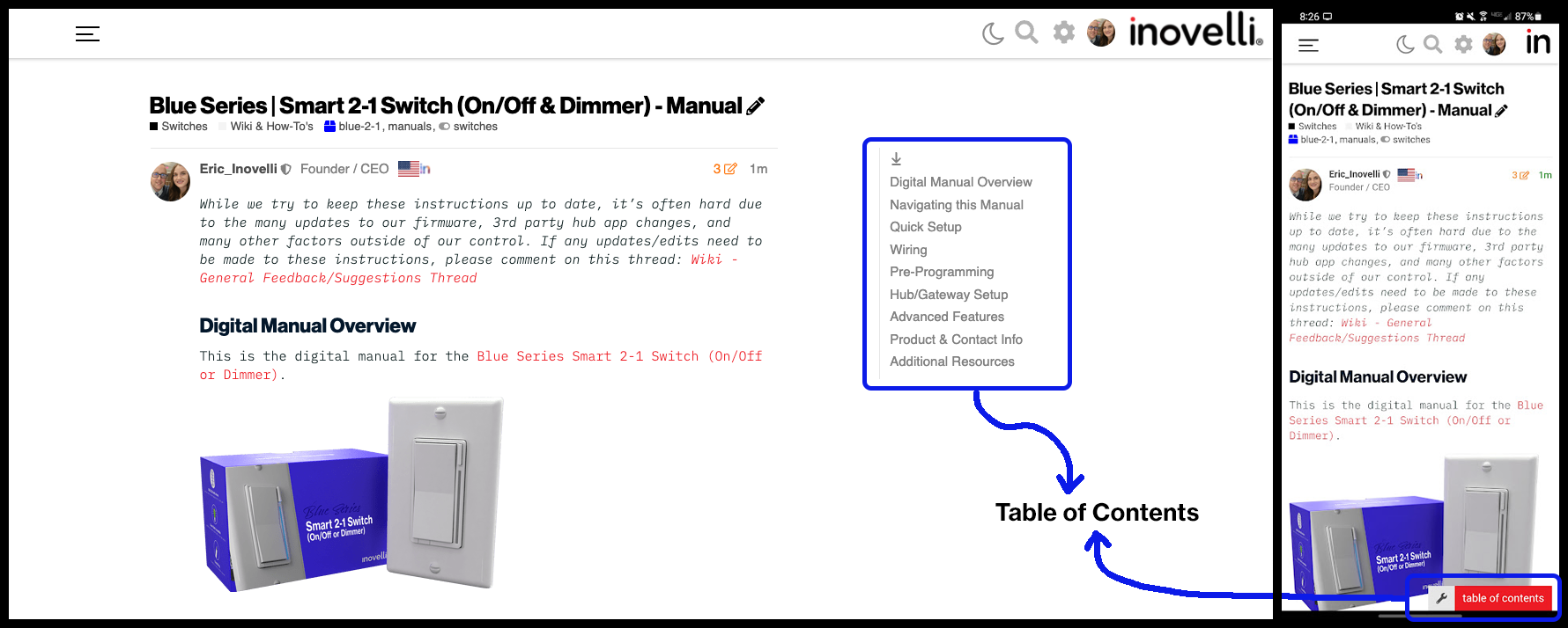
Navigating this Manual
For desktop users, the, “Table of Contents” is located to the right of the screen, whereas for mobile users, it can be found at the bottom of the screen.
NOTE: If you do not see the table of contents, click here: Resources | Blue Series Smart 2-1 Switch (On/Off & Dimmer) - Manual
Please click on any of the sections to get started. We recommend working your way down as it follows an intentional flow that is user friendly and hub/gateway specific.
As always, any questions, please see the Additional Resources links section or submit a ticket, we’re happy to help.
Quick Setup
Other Hub Setup redirects here. Please follow the Quick Setup instructions.
This section assumes the following:
- Your switch is wired correctly and works locally (at the switch)
- You know how to initiate the Zigbee pairing process on your hub.
If you haven’t wired your switch yet and are unsure how, please visit the Wiring section and come back here when completed.
Additionally, if you do not know how to initiate the Zigbee pairing process on your hub or this is your first time installing this switch, we suggest going to the Hub/Gateway Setup section for full installation instructions specific to your hub.
Please select whether you’d like to read the written instructions or watch the video below:
Written
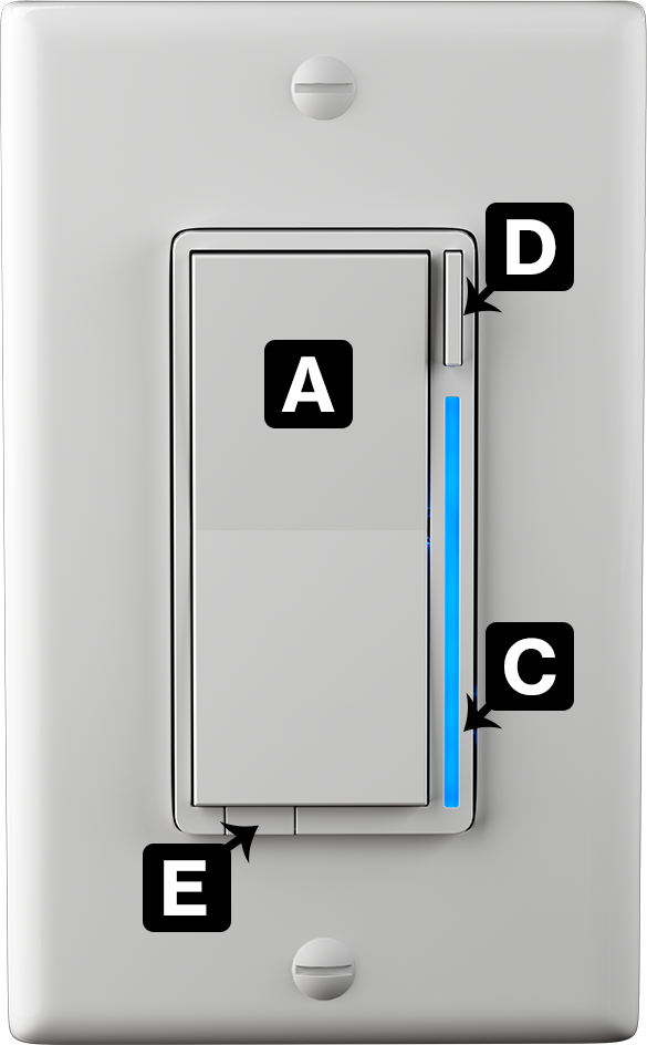
To begin, make sure the LED Bar (C) is pulsing blue.
This can be done by either flipping your electrical breaker off and then on, or by pulling out and pushing back in the air-gap button (E).
If neither of these methods work, you may factory reset the switch by holding down the config button (D) followed immediately by the top of the paddle (A) for 20 seconds until the LED Bar (C) turns/flashes red. Then release the config button (D) followed by the top of the paddle (A) and the LED Bar (C) will start pulsing blue.
Once the LED Bar (C) is flashing blue, start the Zigbee pairing process on your compatible hub. If successful, the LED Bar (C) will turn/flash green.
Video
Coming Soon
Getting to Know Your Switch
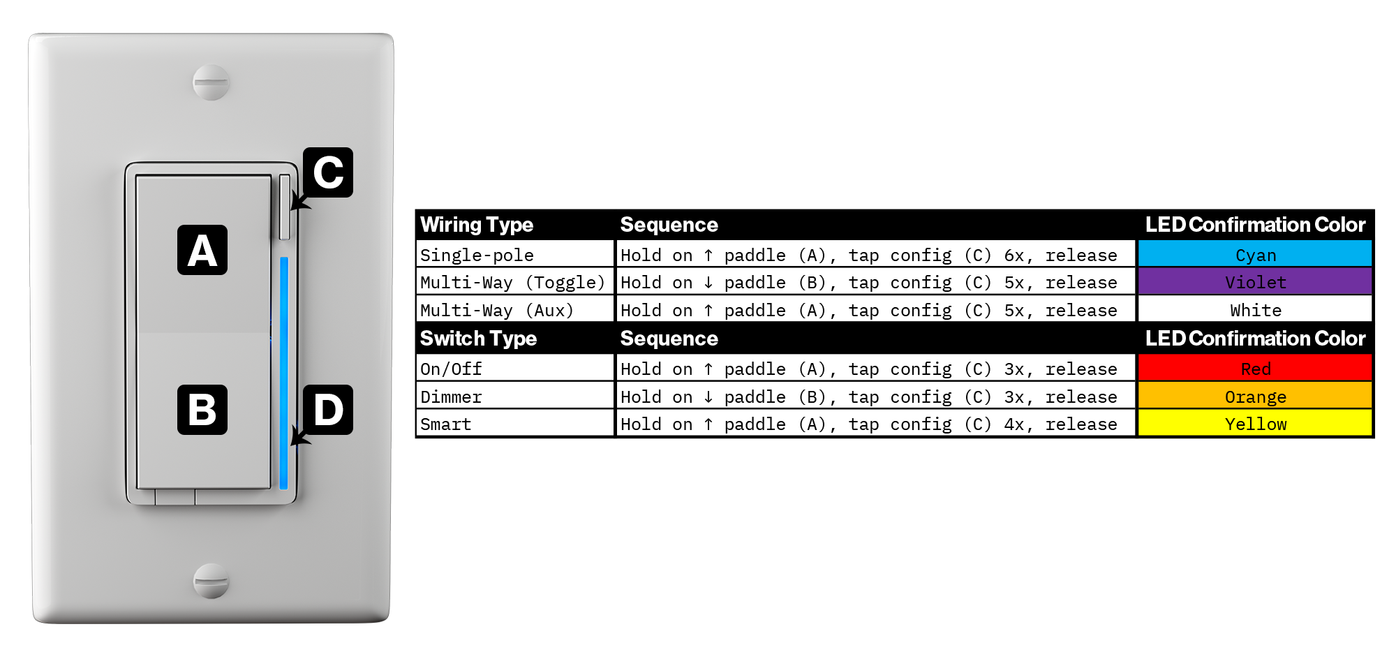
Please use the diagram to the left to better understand your smart switch. While this switch has a ton of advanced features, it operates just like a normal light switch, allowing you to turn it on, off or dim like you would a non-smart switch.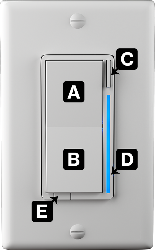
A. Light On / Increase Dim % Level
Tap 1x to turn on your light or hold to increase the brightness level (dim percentage). In addition, it can be used to activate scene control (multi-taps and holds) where up to 7 scenes can be added*.
*Hub must support these features.
B. Light Off / Decrease Dim % Level
Tap 1x to turn off your light or hold to decrease the brightness level (dim percentage). In addition, it can be used to activate scene control (multi-taps and holds) where up to 7 scenes can be added*.
*Hub must support these features.
C. Config / Favorites Button
Used to configure certain parameters of the switch. In addition, it can be used to activate scene control (multi-taps and holds) where up to 7 scenes can be added*.
*Hub must support these features.
D. RGB LED Bar
Multi-functional LED bar that shows the % level at which your switch is at. In addition, it can be used as a notifier* for various events (ie: turn red when alarm is armed, pulse purple if garage is left open, etc).
E. Air Gap
This can be pulled out to cut power to the load and is there for safety purposes.
Quick Tap Sequences
If you are using your switch as a Dimmer or Multi-Way setup, please see the quick tap sequences below or visit the Pre-Setup section for more details.
NOTE: Single-Pole and On/Off are the default settings, but are shown here for reference.
Wiring
IMPORTANT: Consult a qualified electrician if necessary as we are unable to give wiring advice outside of schematics.
NOTE: If you are familiar with wiring and just want to skip to the schematics, please click this link to be taken to them: 2-1 Switch Wiring Schematics
Safety Reminder
If you are unsure how electrical circuits work, please do not try installing this device. As exciting as it is to have a smart switch installed, it can be dangerous and even life-threatening if you do not install it correctly. Improper installation will void the product’s warranty.
Please read through the warning and vocabulary sections below before installing your switch. We can’t stress enough how dangerous installation can be if you don’t know what you’re doing.
Warnings
Please click on the below drop-downs to see the various warnings related to wiring. Remember, if you are unsure of what you’re doing, please consult with an electrician, it’s not worth getting injured.
English
Caution - Please Read: This device (VZM31-SN) is intended for installation in accordance with the National Electric Code and local regulations in the United States, or the Canadian Electrical Code and local regulations in Canada. If you are unsure or uncomfortable about performing this installation consult a qualified electrician.This product is made for indoor use only and is not designed or approved for use on power lines other than 120VAC, 60Hz, single phase. Attempting to use this VZM31-SN on non-approved power lines may have hazardous consequences.
Other Warnings: Risk of Fire, Electrical Shock & Burns
Recommended Installation Practices: Use only indoors or in an outdoor rated box. Turn off the circuit breaker. Installing this switch and module with the power on will expose you to dangerous voltages. Connect only copper or copper-clad wire to the switch or module.
To reduce the risk of overheating and possible damage to other equipment, use the VZM31-SN load output to control no more than 600 Watts (Incandescent) or 300 Watts (LED) or 150 Watts (CFL). Dimming an inductive load (by connecting to the light load wire), such as a fan or transformer, could cause damage to the dimmer, the load bearing device, or both.
NOTE: This switch is not certified by UL to be used by any sort of inductive load (exhaust/ceiling fans).
To install your 2-1 Switch (VZM31-SN), you’ll need to identify the following four wires (NOTE: Neutral is not mandatory, but recommended):
- Line: Usually black and can also be called the, “hot” or “live” and carries 120VAC electricity into the electrical box
- Neutral (Not Mandatory): Usually white and is commonly daisy chained from box to box, usually appearing as a white wire bundle.
- Load: Usually black, blue or red
- Ground: Bare copper wire or metal fixture (if grounded)
If you are having difficulties identifying wires, please consult an electrician.
Medical Equipment: Please do not use this switch to control Medical or Life Support equipment. ZigBee devices should never be used to control the On/Off status of Medical and/or Life Support equipment.
Français
Attention – Information importante : Cet appareil (VZM31-SN) est conçu pour être installé conformément au « National Electric Code » et aux réglementations locales aux États-Unis, ou au Code canadien de l’électricité et aux réglementations locales canadiennes. Si vous ne vous sentez pas à l’aise ou qualifiés pour effectuer cette installation, veuillez consultez un électricien qualifié. Ce produit est conçu pour une utilisation intérieure uniquement et n’est pas conçu ou approuvé pour une utilisation avec une ligne électrique ayant un voltage autre que 120 VCA, 60 Hz, monophasé. L’utilisation du VZM31-SN avec une ligne électrique non approuvée peut avoir des résultats dangereux.
Autres avertissements : Risque d’incendie, de choc électrique et de brûlures
Pratiques d’installation recommandées : Utiliser uniquement à l’intérieur ou à l’extérieur dans une boîte adaptée aux conditions extérieures. Éteignez le disjoncteur. L’installation de cet interrupteur et de ce module alors que le courant est allumé vous exposera à des tensions dangereuses. Connectez uniquement un fil de cuivre ou gainé de cuivre au commutateur ou au module.
Pour réduire le risque de surchauffe et d’endommager d’autres équipements, il est important de connecter des lumières incandescentes ayant moins de 600 watts, des lumières DEL ayant moins de 300 watts, des ampoules fluocompactes ayant moins de 150 watts ou un ventilateur utilisant moins de 1 ampère et ce dernier avec l’interrupteur en mode marche/arrêt uniquement. La gradation d’une charge inductive, comme un ventilateur ou un transformateur, pourrait endommager le gradateur, l’interrupteur ou les deux appareils. Veuillez régler l’interrupteur en mode marche/arrêt si vous utilisez un ventilateur.
Pour installer votre interrupteur 2 en 1 (VZM31-SN), vous devrez identifier les quatre fils suivants (REMARQUE: le neutre est optionnel, mais recommandé) :
- Ligne : généralement noire et peut également être appelée « chaud » ou « sous tension » et transporte l’électricité 120 VCA dans le boîtier électrique
- Neutre (optionnel) : habituellement blanc et connecté en série d’une boîte à l’autre, les fils sont habituellement attachés ensemble dans la boîte électrique
- Charge : habituellement noire, bleue ou rouge
- Mise à terre : fil de cuivre nu ou boîtier métallique (si celui-ci est mis à la terre)
Si vous rencontrez des difficultés à identifier les fils, veuillez consulter un électricien.
Équipement médical : Veuillez ne pas utiliser cet interrupteur pour contrôler de l’équipement médical ou nécessaire à la survie. Les appareils ZigBee ne doivent jamais être utilisés pour contrôler la marche or l’arrêt d’équipement médical et/ou nécessaires à la survie.
Vocabulary
Before we go into the actual steps, it’s important to be familiar with the vernacular used. Please familiarize yourself with the following terms (click the drop-downs):
Electrical Terms
- Line: This is your hot wire (120V) - also known as your, “live” wire
- Wiring Color: Black (however, sometimes it can be white/black or red/black)
- Load: This is the wire that runs from your light switch to what you’re controlling (ie: bulb(s))
- Wiring Color: Black (however, sometimes it can be white)
- NOTE: A load can be made up of multiple bulbs or fixtures – what’s important is to understand what turns on and off when you flip your switch.
- Neutral: This is the wire that carries current back to the power source.
- Wiring Color: White (or sometimes gray)
- NOTE: You may not have this wire in your house – if you do have them, they are often clumped together at the back of your gang-box
- Ground: This is the wire that provides a path directly to ground (earth) should the current need it
- Wiring Color: Green or copper
Wiring Terms
NOTE: In all cases below, when we say, “load”, it can be one bulb, multiple bulbs, etc – think of it as, “whatever turns off when you flip a switch”
- Single-Pole: One switch controlling one load
- 3-Way: Two switches controlling the same load
- 4-Way: Three switches controlling the same load
- 5-Way: Four switches controlling the same load
- Multi-Way: For simplicity sake, we will use this term when referring to 3-Way, 4-Way, or 5-Way setups as the switch is programmed the same regardless
Other Terms
- Dumb Switch: Refers to your existing switch (ie: the switches you had before replacing with a smart switch)
- Aux Switch: Refers to the Inovelli Aux Switch [INSERT HYPERLINK TO PRODUCT PAGE] or the GE, Honeywell, or HomeSeer versions (sometimes these are also called an, “add-on” switch)
- Neutral Setup: Refers to having a neutral wire present in your wiring setup
- Non-Neutral Setup: Refers to not having a neutral wire present in your wiring setup
Installation Instructions
After reading the warning and vocabulary sections, it’s time to figure out what kind of setup you have.
- Steps 1-3: Write down (or memorize) the answers in each of these sections
- Step 4: Use the answers from Steps 1-3 to determine whether or not your setup is compatible using the compatibility chart
- Step 5: After determining your setup is compatible in Step 4, this step will help you find the correct schematic for your setup
Remember - do not attempt to wire this switch if you are unsure of what you’re doing. Please hire an electrician.
1. Determining Wiring Type
The first step is to determine how many switches control your load(s) (aka: light(s)).
Using the diagram on below, please determine what your wiring type is and remember this selection:
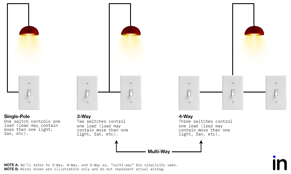
Once you’ve determined how many switches control your load, please select from one of the underlined options below and remember it.
- Single-Pole: One switch controls one load (load may contain more than one light, etc).
- Multi-Way: Two or more switches control one load (load may contain more than one light, etc). We will use the term, “multi-way” instead of 3-Way, 4-Way, 5-Way, etc as the programming of the switch is the same regardless.
WIRING TYPE (REMEMBER THIS): Single-Pole or Multi-Way
2. Determining Switch Layout
NOTE: If you determined your switch is a single-pole, you may skip to step #3. This step is for multi-way setups only.
Using the diagram below, please determine what your wiring layout is and remember this selection:
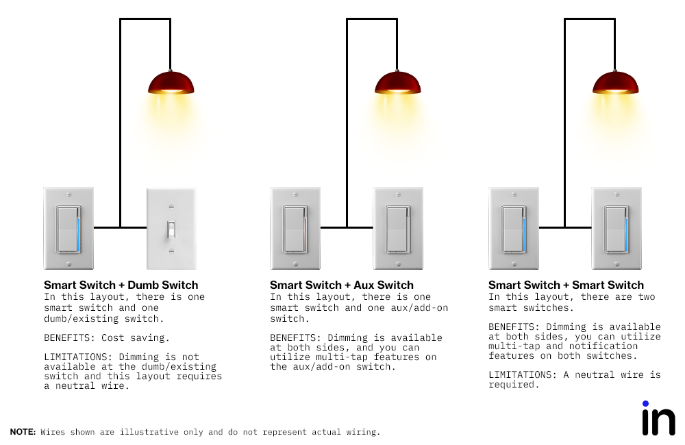
Once you’ve determined your switch layout, please select from one of the underlined options below and remember it.
- Smart Switch + Toggle Switch: One smart switch and one (or more) toggle/existing switch (one already in your wall).
- Smart Switch + Aux Switch: One smart switch and one (or more) add-on (aux) switch (AUX01).
- Smart Switch + Smart Switch: Two (or more) smart switches.
You may not mix/match (ie: Smart + Aux + Toggle) in the same circuit.
SWITCH LAYOUT (REMEMBER THIS): Toggle, Aux, or Smart Switch(es)
3. Determining AC Power Type
In this step, we will determine if you have a neutral wire, which is typically white and located in the back in your switch gang-box (typically in a bundle of wires tied together).
Here are some signs you may have a neutral wire:
- If your house was built in the mid-1980’s or later
- If there is an outlet (receptacle) near the switch
- If switches are in the same gang-box (regardless of the year the house was built)
To check if you have a neutral wire or not, please follow the below instructions:
After turning off your breaker, pull out the switches (WARNING: there may be multiple circuits in one gang-box – please ensure all circuits are turned off). Check the back of your gang-box for a bundle of white wires. These are typically neutrals. An example is shown below.

Once you’ve determined if you have a neutral wire or not, please select from one of the underlined options below and remember it.
- Neutral = Neutral wire present
- No Neutral = No neutral wire present
AC POWER TYPE: Neutral or No Neutral
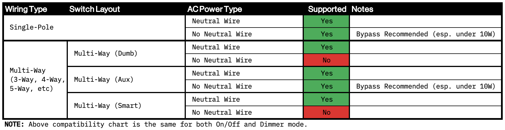
4. Compatibility
In this step, we will determine if your switch can be installed with your current wiring setup. If not, you can see some alternate solutions on how to accomplish compatibility.
Taking the answers you circled in Steps 1-3, please see the chart below to see if your switch is compatible with your setup.
Example
If you circled, “Multi-Way”, “Toggle Switch” and “Neutral”, you will see that your wiring is compatible. However, if you circled, “Multi-Way”, “Toggle Switch” and “No Neutral”, you will see that your wiring is not compatible and you will need to purchase an auxiliary switch (inov.li/aux).
5. Switch Installation
The last step is to physically install your switch. After you’ve determined your wiring type, switch layout, AC Power type and whether or not you have a compatible setup, it’s time to look at the wiring schematics and install your switch.
To ensure our schematics are kept up to date, we house them in one location. Please click on the link below to be taken to the schematics page (new tab will open):
Use the values you circled in first three steps above (ie: Wiring Type, Switch Layout, and AC Power Type) to find your corresponding schematic.
Once your switch is wired correctly, please restore power. If your switch is wired in a multi-way setup and/or you want the switch to be a dimmer, you must program your switch to work in the Pre-Programming section below. It will not work properly without programming it.
IMPORTANT: Once power is restored to your switch, you should see the LED bar pulsing blue – this means it is looking for a hub to pair to. If you want to quickly pair your switch, please put your hub in pairing mode. We recommend moving to the Pre-Programming section first to ensure your switch works properly before pairing.
Pre-Setup
NOTE: If you intend to use your switch as an on/off switch and in a single-pole setting, you may skip this section. If you intend to use your switch as a dimmer and/or in a multi-switch setup, please proceed with the instructions below.
Now that you’ve wired your switch and restored power, it’s time to program it to work as you intended it to.
We’ll first start by telling the switch what wiring configuration it’s in (ie: Single-Pole, Multi-Way (Toggle) or Multi-Way (Aux). Next, we’ll tell the switch the mode it should be in (ie: On/Off, Dimmer or Smart to Smart). Follow the Quick-Tap chart below and/or click the drop-down to learn more about get started. Reminder, this is only needed if you are programming your switch to be a dimmer and/or in multi-way.
Written Example
Let’s say you want your switch to be a dimmer switch and you have it wired in a multi-switch setting using a toggle (dumb) switch along with your Inovelli 2-1 switch.
Using the chart below, you would first hold down on the bottom part of the paddle (C), while simultaneously tapping the config button (A) 3x and then releasing both the paddle and config button. The LED Bar will confirm the setting by blinking/turning orange.
Next, to program the switch to work in a multi-switch setup using a toggle (dumb) switch, you would then hold down on the bottom part of the paddle (C), while simultaneously tapping the config button (A) 5x and then releasing both the paddle and config button. The LED Bar will confirm the setting by blinking/turning violet.
Video Examples
Please click on the corresponding URL’s to see how to properly setup your switch. NOTE: URL’s will open to a new tab.
- Single-Pole
- Multi-Way (Toggle)
- Multi-Way (Aux)
- On/Off
- Dimmer
- Smart
Confirm that your switch works properly in the setup you desire and if so, move onto the next section: Hub/Gateway Setup.
Hub/Gateway Setup
To save space and keep this page from being extremely long, hub/gateway setup instructions will live on separate pages. This also helps us structure our Knowledge Base via the tag system (if everything was listed on one thread, it would be hard to search for specific terms as you’d have to sort through the entire thread to find it).
That said, please click the links below to be taken to the setup pages for your hub/gateway. If you don’t see your hub/gateway, please see the Quick Setup instructions above and reach out to us so we can work with you to add instructions so others can benefit.
Amazon Echo
SmartThings (Aeotec or Samsung)
Home Assistant - ZHA
Home Assistant - Zigbee2mqtt
Hubitat
Advanced Features
IMPORTANT: The advanced features shown below are what is built into the switch firmware, and may or may not be supported by your hub/gateway. If something is not working properly, please let us know and we and/or the community will investigate.
Parameter List
Please see below for the full parameter list. In each section, click, “More Details” to understand more how the parameter works. Each time we update the firmware, we will create a new section and you can click on a dropdown based on the firmware version you have. To understand what firmware version you have, you can look at the date code on the top left of the switch (or check on your hub/gateway’s user interface).
Firmware - v01020200 (2.0) (Present)
NOTE: Some parameters are only available in dimmer mode and are called out in the, “About” section with the words, “Dimmer Mode Only”.
| # | About | Description | Range | Default | Size (Bytes) |
|---|---|---|---|---|---|
| 1 | Dimming Speed (↑) - Remote Dimmer Mode Only |
How fast or slow the light turns on when you change the dim level remotely (ie: dimming from 10-20%, 60-80%, etc)More Details0 = Instant On 5 = Fast (500ms) 126 = Slow (12.6s) IF USING A DUMB SWITCH: This parameter will not work when pressing the dumb switch manually. NOTE: Third party code may need to be implemented (device handler, driver, etc) for this to work properly. Some hubs may not support this feature. |
0-126 | 25 (2.5s) |
1 |
| 2 | Dimming Speed (↑) - Local Dimmer Mode Only |
How fast or slow the light the light turns on when you hold up on the switch (ie: dimming from 10-20%, 60-80%, etc)More Details0 = Instant On 5 = Fast (500ms) 126 = Slow (12.6s) 127 = Sync to Parameter 1 IF USING A DUMB SWITCH: This parameter will not work when pressing the dumb switch manually. |
0-127 | 127 | 1 |
| 3 | Ramp Rate (Off → On) - Remote Dimmer Mode Only |
How fast or slow the light turns on when you remotely bring the switch from Off to OnMore Details0 = Instant On 5 = Fast (500ms) 126 = Slow (12.6s) 127 = Sync to Parameter 1 NOTE: Third party code may need to be implemented (device handler, driver, etc) for this to work properly. Some hubs may not support this feature. |
0-127 | 127 | 1 |
| 4 | Ramp Rate (Off → On) - Local Dimmer Mode Only |
How fast or slow the light turns on when you press the switch up 1x to bring from Off to OnMore Details0 = Instant On 5 = Fast (500ms) 126 = Slow (12.6s) 127 = Sync to Parameter 3 |
0-127 | 127 | 1 |
| 5 | Dimming Speed (↓) - Remote Dimmer Mode Only |
How fast or slow the light turns off when you change the dim level remotely (ie: dimming from 80-60%, 20-10%, etc)More Details0 = Instant Off 5 = Fast (500ms) 126 = Slow (12.6s) 127 = Sync to Parameter 1 IF USING A DUMB SWITCH: This parameter will not work when pressing the dumb switch manually. NOTE: Third party code may need to be implemented (device handler, driver, etc) for this to work properly. Some hubs may not support this feature. |
0-127 | 127 | 1 |
| 6 | Dimming Speed (↓) - Local Dimmer Mode Only |
How fast or slow the light the light turns off when you hold down on the switch (ie: dimming from 80-60%, 20-10%, etc)More Details0 = Instant Off 5 = Fast (500ms) 126 = Slow (12.6s) 127 = Sync to Parameter 2 IF USING A DUMB SWITCH: This parameter will not work when pressing the dumb switch manually. |
0-127 | 127 | 1 |
| 7 | Ramp Rate (On → Off) - Remote Dimmer Mode Only |
How fast or slow the light turns on when you remotely bring the switch from Off to OnMore Details0 = Instant Off 5 = Fast (500ms) 126 = Slow (12.6s) 127 = Sync to Parameter 3 NOTE: Third party code may need to be implemented (device handler, driver, etc) for this to work properly. Some hubs may not support this feature. |
0-127 | 127 | 1 |
| 8 | Ramp Rate (On → Off) - Local Dimmer Mode Only |
How fast or slow the light turns on when you press the switch up 1x to bring from Off to OnMore Details0 = Instant Off 5 = Fast (500ms) 126 = Slow (12.6s) 127 = Sync to Parameter 4 |
0-127 | 127 | 1 |
| 9 | Minimum Dim Level Dimmer Mode Only |
Minimum level the light switch will dim toMore DetailsLower the numeric value = lower the min dim level (1 = ~1%) Higher the numeric value = higher the min dim level (254 = ~99%) Great for fixing flickering bulbs or calibrating the bulb if it shuts off prior to 1% HUB NOTE: Some hub user interfaces may show a range of 1-99 as available inputs. This is because it’s easier to think in terms of 0-100% instead of calculating what number out of 255 is equal to x%. |
1-254 | 1 | 1 |
| 10 | Maximum Dim Level Dimmer Mode Only |
Maximum level the light switch will dim toMore DetailsLower the numeric value = lower the max dim level (2 = ~2%) Higher the numeric value = higher the max dim level (255 = ~100%) NOTE: Great for calibrating a bulb when it reaches maximum level before 100% HUB NOTE: Some hub user interfaces may show a range of 2-100 as available inputs. This is because it’s easier to think in terms of 0-100% instead of calculating what number out of 255 is equal to x%. |
2-255 | 255 | 1 |
| 11 | Invert Switch | Inverts the switch (Tapping ↓ = On, Tapping ↑ = Off)More Details0 = Disabled 1 = Enabled |
0-1 | 0 | 1 |
| 12 | Auto Off Timer | Automatically turns the switch off after x amount of secondsMore Details0 = Disabled 1 = 1s 32767 = 32767s |
0-32767 | 0 | 2 |
| 13 | Default Level - Local Dimmer Mode Only |
The default dim level the switch goes to when turned on locally (at the switch)More Details0 = Off 1-254 = Specific level on 255 = Returns to prior state it was before being turned off HUB NOTE: Some hub user interfaces may show a range of 1-100 as available inputs. This is because it’s easier to think in terms of 0-100% instead of calculating what number out of 255 is equal to x%. |
0-255 | 255 | 1 |
| 14 | Default Level - Remote Dimmer Mode Only |
The default dim level the switch goes to when powered on via a remote commandMore Details0 = Off 1-254 = Specific level on 255 = Returns to prior state it was before being turned off HUB NOTE: Some hub user interfaces may show a range of 1-100 as available inputs. This is because it’s easier to think in terms of 0-100% instead of calculating what number out of 255 is equal to x%. |
0-255 | 255 | 1 |
| 15 | Level After Power Restored | When power is restored, the switch reverts to either On, Off, or Last LevelMore Details0 = Off 1-254 = Specific level on 255 = Returns to level before power outage |
0-255 | 255 | 1 |
| 17 | LED Indicator Timeout | Changes the amount of time (in seconds) the RGB Bar shows the Dim levelMore Details0 = Always off 1 = 1 second after level is adjusted 10 = 10 seconds after level is adjusted 11 = Always on |
0-11 | 11 | 1 |
| 18 | Active Power Reports | The power level change that will result in a new power report being sent in wattage (W)More Details0 = Disabled 1 = 0.1W change 10 = 1W change 100 = 10W change 32767 = 3276.7W |
0-32767 | 10 | 2 |
| 19 | Periodic Power & Energy Reports | Time period between consecutive power and energy reports being sent (in seconds)More Details0 = Disabled 1 = 1s 32767 = 32767s NOTE: Timer resets after every report is sent |
0-32767 | 3600 | 2 |
| 20 | Energy Reports | The energy level change that will result in a new energy report being sent in kilowatt hours (kWh)More Details0 = Disabled 1 = 0.01kWh 10 = 0.1kWh 100 = 1kWh 32767 = 327.67kWh |
0-32767 | 10 | 2 |
| 21 | AC Power Type | Select whether you are wiring your switch with or without a neutral wireMore Details0 = No-Neutral 1 = Neutral |
0-1 | 1 | 1 |
| 22 | Switch Type | Select what type of installation you haveMore Details0 = Single-Pole (ie: one switch) 1 = Multi-Way (Dumb Switch) 2 = Multi-Way (Auxiliary Switch) |
0-2 | 0 | 1 |
| 50 | Switch Delay | Adjusts the delay between taps in 100ms increments 0 = 0ms (disables multi-tap scene control), 1 = 100ms, 2 = 200ms, 9 = 900ms) |
0-9 | 7 | 1 |
| 52 | Smart Bulb Mode | Enables or disables smart bulb modeMore Details0 = Disable SBM 1 = Enable SBM |
0-1 | 0 | 1 |
| 95 | LED Indicator Color (When On) - LED #'s 1-7 | This will set the default color of the LED Bar (all 7 LED’s) when the switch is onMore DetailsCalculated by using a hue color circle (Value / 255 * 360). See website for more info. |
0-255 | 170 (Blue) | 3 |
| 96 | LED Indicator Color (When Off) - LED #'s 1-7 | This will set the default color of the LED Bar (all 7 LED’s) when the switch is offMore DetailsCalculated by using a hue color circle (Value / 255 * 360). See website for more info. |
0-255 | 170 (Blue) | 3 |
| 97 | LED Indicator Intensity (When On) - LED #'s 1-7 | This will set the intensity (ie: how bright it is) of the LED bar (all 7 LED’s) when the switch is onMore Details0 = Off 10 = Low 50 = Medium 100 = High |
0-100 | 33 | 1 |
| 98 | LED Indicator Intensity (When Off) - LED #'s 1-7 | This will set the intensity (ie: how bright it is) of the LED bar (all 7 LED’s) when the switch is offMore Details0 = Off 10 = Low 50 = Medium 100 = High |
0-100 | 1 | 1 |
| 256 | Local Protection | Determines whether or not the load of the switch can be controlled via paddle presses (locally)More Details0 = Disabled 1 = Enabled |
0-1 | 0 | 1 |
| 257 | Remote Protection | Determines whether or not the load of the switch can be controlled via RF (remote)More Details0 = Disabled 1 = Enabled |
0-1 | 0 | 1 |
| 258 | Switch Mode (Dimmer or On/Off) | Determines the mode of the switch (On/Off or Dimmer)More Details0 = On/Off 1 = Dimmer |
0-1 | 0 | 1 |
| 259 | One LED Mode | Switch only shows LED #1 and does not show LED #'s 2-6 – this mimics the Red Series On/Off switchMore Details0 = Disabled 1 = Enabled |
0-1 | 0 | 1 |
| 260 | Firmware Progress LED | During a firmware update, the switch will show the progress on the LED BarMore DetailsEXAMPLE: 1/4 LED Bar shown = 25%, 1/2 LED Bar shown = 50%, 3/4 LED Bar shown = 75% 0 = Disable, 1 = Enable |
0-1 | 1 | 1 |
| 261 | Disable Relay, “Click” Sound | In neutral on/off setups, the default is to have a clicking sound to notify you that the relay is open or closed. You may disable this sound by creating a, “simulated” on/off where the switch only will turn onto 100 or off to 0.More Details0 = Disabled (Click Sound On) 1 = Enabled (Click Sound Off |
0-1 | 0 | 1 |
Local Configuration
Animated Notifications
Animated notifications refers to the LED bar notifying you of certain events either by lighting up a certain color, or by showing some sort of animation. An example would be if there’s severe weather detected, the LED bar could pulse red or if you left the garage door open past 10pm, the LED bar could chase purple.
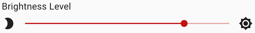
Each animation can be customized to how you’d like using the following variables (select a number within each variable):
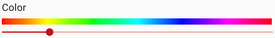
Duration
1-59: Each interval = 1 second
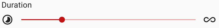
60-119: Each interval = 1 minute
120-254: Each interval = 1 hour
255: Indefinite duration
Animation Effect
Click on each to see a visual (NOTE: 0 is off and 255 is clear).
1: Solid
2: Fast Blink
3: Slow Blink
4: Pulse
5: Chase
6: Open-Close
7: Small-Big
Since setup instructions are different for each hub/gateway, please click on the corresponding links below (opens a new tab).
Amazon Echo - Not available
SmartThings (Aeotec or Samsung)
Home Assistant - ZHA
Home Assistant - Zigbee2mqtt
Hubitat
Scene Control
Scene control refers to activating a scene via your light switch. An example would be double-tapping down to turn off all your lights, set the temperature to 68, lock the doors, arm the alarm system for bedtime. This switch provides up to 20 different options to create custom scenes.
Since setup instructions are different for each hub/gateway, please click on the corresponding links below.
Amazon Echo - Not available
SmartThings (Aeotec or Samsung)
Home Assistant - ZHA
Home Assistant - Zigbee2mqtt
Hubitat
2-1 Switch Button Mapping
Button mapping simply means assigning virtual buttons to events. In other words, your switch has 21 different buttons built into it and you need to “map” the correct button to a scene (you setup via your hub) so that when you press a specific button, your scene runs.
Regardless of the hub/gateway used, the button (or scene) mapping will be the same. In order to understand how to read the chart below, let’s use an example.
Taking the example from above, let’s say you want to create a bedtime scene where when you tap down on your light switch 2x, all of your lights turn off, your thermostat turns to 68, your doors lock and your alarm system is changed to armed.
We first need to start by understanding how to set the correct button (ie: the tap down on light switch paddle 2x). Each switch has, “virtual buttons” built into it. In other words, you can physically see and touch the up/down and config/favorite buttons, but the switch takes it a step further and adds in multi-taps which have a, “virtual button number” assigned to them. The chart below will help you map the action that you want (double-tap down) with the “virtual button number” so that your hub/gateway understands what scene to activate.
In reading the chart below, we can see that if we want a scene to activate when, “tapping down on the light switch paddle 2x”, you would select, “Button 2 - Held” when your hub/gateway asks (don’t worry about the code section, that’s more for programming purposes).
| Action | Button # | Event | Code |
|---|---|---|---|
| Tap Up on Light Paddle 1x | 1 | Pushed | 0x0200 |
| Tap Up on Light Paddle 2x | 2 | Pushed | 0x0203 |
| Tap Up on Light Paddle 3x | 3 | Pushed | 0x0204 |
| Tap Up on Light Paddle 4x | 4 | Pushed | 0x0205 |
| Tap Up on Light Paddle 5x | 5 | Pushed | 0x0206 |
| Hold Up on Light Paddle | 6 | Pushed | 0x0202 |
| Release Up on Light Paddle | 7 | Pushed | 0x0201 |
| Tap Down on Light Paddle 1x | 1 | Held | 0x0100 |
| Tap Down on Light Paddle 2x | 2 | Held | 0x0103 |
| Tap Down on Light Paddle 3x | 3 | Held | 0x0104 |
| Tap Down on Light Paddle 4x | 4 | Held | 0x0105 |
| Tap Down on Light Paddle 5x | 5 | Held | 0x0106 |
| Hold Down on Light Paddle | 6 | Held | 0x0102 |
| Release Down on Light Paddle | 7 | Held | 0x0101 |
| Tap Config Button 1x | 8 | Pushed | 0x0300 |
| Tap Config Button 2x | 9 | Pushed | 0x0303 |
| Tap Config Button 3x | 10 | Pushed | 0x0304 |
| Tap Config Button 4x | 11 | Pushed | 0x0305 |
| Tap Config Button 5x | 12 | Pushed | 0x0306 |
| Hold Config Button | 13 | Pushed | 0x0302 |
| Release Config Button | 14 | Pushed | 0x0301 |
Now that you have the correct button, please proceed to setting up your scene via the instructions located at the beginning of the Scene Control section.
NOTE: The 2-1 switch can detect and will mimic multi-presses from the Inovelli Aux/Add-On switch. In other words, if you double-tap down on the Aux/Add-On switch, the 2-1 switch will send a, “Button 2 - Held” event to the hub. Just another reason to purchase one: Blue Series Smart 2-1 Switch (On/Off or Dimmer)
Smart Bulb Mode
Smart Bulb Mode allows constant power to be “locked in” to your smart bulb, allowing you to control it directly from the light switch without cutting power. In other words, smart bulbs require 100% power to them in order to stay in communication with your hub/gateway and if they’re put on traditional light switches, when someone turns off the switch, there is no longer power going to the bulb and it’s rendered useless (because it can’t communicate to the hub).
Using Smart Bulb Mode, in conjunction with Zigbee Bindings and/or Scene Control will allow you to use your smart switch like a normal light switch in that you’ll be able to turn on/off and dim your smart bulb.
Further Explanation
We realize this can be semi-confusing, so please see below for a couple examples on how Smart Bulb Mode can be used in conjunction with either Zigbee Bindings and/or Scene Control.
Our recommendation would be to use Smart Bulb Mode with Zigbee Bindings AND Scene Control if your hub supports it.
-
Smart Bulb Mode will allow your switch to lock in full power to your smart bulb(s)
-
Zigbee Bindings will allow you to directly control your smart bulb and turn it on/off and dim very quickly (bypasses the hub/gateway)
-
Scene Control will allow you to multi-tap to change colors quickly (ie: double-tap your config button to change your lights to purple, or triple-tap to set the Aurora scene)
A real-life example of using all three (Smart Bulb Mode, Zigbee bindings, and Scene Control) would be the following:
Let’s say you have a family room smart light switch (Inovelli Zigbee switch) that is directly wired to some overhead lights (Zigbee bulbs) above your TV and you want to be able to have those lights dim, turn on/off and change colors depending on if you’re watching a movie or not.
-
First step is to set your switch to Smart Bulb Mode (see directions here) – this will ensure constant power to your bulbs.
-
Next, setup Zigbee bindings (NOTE: Your Zigbee bulbs and switch need to be on the same network) and this will allow your switch to directly talk to your bulb(s) bypassing the hub – it will still report to the hub, but it will also talk directly to the bulb(s)) – this will allow you to turn on/off and dim your bulb(s).
-
Finally, and this is fully customizable, you’ll setup Scene Control so that you can quickly change between normal warm/cool lights when movies are not playing to ambient lighting when movies are playing. There are 21 different “buttons” you can choose from to assign these scenes to. Let’s say in this case, you make it so that a double-tap on the config button turns your lights to either warm or cool lighting and a triple-tap on the config button turns them to ambient lighting.
Some hubs do not support Zigbee binding (or it’s not fully implemented yet) and you will have to use only Smart Bulb Mode and Scene Control. The same thing can be accomplished in that you’ll be able to turn on/off/dim and change colors of your smart bulb, however the user experience will be slightly different.
Using the same example – you have a family room smart light switch (Inovelli Zigbee switch) that is directly wired to some overhead lights (Zigbee bulbs) above your TV and you want to be able to have those lights dim, turn on/off and change colors depending on if you’re watching a movie or not – here’s how it would be setup:
-
First step is to set your switch to Smart Bulb Mode (see directions here) – this will ensure constant power to your bulbs.
-
Next, use Scene Control to turn on/off, dim and change colors. It could be setup the following way (again, there are 21 different combinations you can choose from, this is the most common):
- 1x Tap Up = Turns on bulb(s) to 100%
- 2x Tap Up = Turns on bulb(s) to 75%
- 3x Tap Up = Turns on bulb(s) to 50%
- 4x Tap Up = Turns on bulb(s) to 25%
- 5x Tap Up = Turns on bulb(s) to 10%
- 1x Tap Down = Turns off bulb(s)
- 2x Tap Config Button = Turns bulb(s) to warm/cool white
- 3x Tap Config Button = Turns bulb(s) to ambient lighting
Since setup instructions are different for each hub/gateway, please click on the corresponding links below.
Amazon Echo - Not available
SmartThings (Aeotec or Samsung)
Home Assistant - ZHA
Home Assistant - Zigbee2mqtt
Hubitat
Zigbee Binding
Zigbee binding refers to two or more Zigbee devices being directly “bound” together which allows for quicker communication by bypassing the hub/gateway. This is most commonly used when you want to create a multi-way setup (3-Way, 4-Way, 5-Way, etc) with all Inovelli smart switches or if you want to control smart bulb(s) from a smart switch.
Since setup instructions are different for each hub/gateway, please click on the corresponding links below.
Amazon Echo - Not available
SmartThings (Aeotec or Samsung)
Home Assistant - ZHA
Home Assistant - Zigbee2mqtt
Hubitat
Product & Contact Info
FCC/IC Statements
Please click on the below drop-downs to see the FCC/IC statements.
FCC - English
FCC Caution: Any changes or modifications not expressly approved by the party responsible for compliance could void the user’s authority to operate this equipment. This device complies with Part 15 of the FCC Rules. Operation is subject to the following two conditions: (1) This device may not cause harmful interference, and (2) this device must accept any interference received including interference that may cause undesired operation.
NOTE: This equipment has been tested and found to comply with the limits for a Class B digital device, pursuant to Part 15 of the FCC Rules. These limits are designed to provide reasonable protection against harmful interference in a residential installation.
This equipment generates, uses and can radiate radio frequency energy and, if not installed and used in accordance with the instructions, may cause harmful interference to radio communications. However, there is no guarantee that interference will not occur in a particular installation. If this equipment does cause harmful interference to radio or television reception, which can be determined by turning the equipment off and on, the user is encouraged to try to correct the interference by one or more of the following measures:
Reorient or relocate the receiving antenna, increase the separation between the equipment and receiver, connect the equipment into an outlet on a circuit different from that to which the receiver is connected or consult the dealer or an experienced radio/TV technician for help. This equipment should be installed and operated with minimum distance 8in (20cm) between the radiator and your body.
IC - English
IC Caution: This device complies with Industry Canada licence-exempt RSS standard(s). Operation is subject to the following two conditions: (1) this device may not cause interference, and (2) this device must accept any interference, including interference that may cause undesired operation of the device.
IC - Français
DECLARATION DE CONFORMITE D’INDUSTRIE CANADA : Ce périphérique a été testé et reconnu conforme aux limites spécifiées dans RSS-210. Son utilisation est soumise aux deux conditions suivantes: (1) il ne doit pas provoquer d’interférences gênantes et (2) il doit tolérer les interférences, notamment celles susceptibles d’en perturber le fonctionnement.
Product Info
Make: Inovelli
Model #: VZM31-SN
Amazon ASIN: TBD
UPC: 850007431174
__
Power: 120V AC, 60Hz
Signal (Frequency): 2.4GHz
Operating Temperature Range: 32-95° F (0-35° C)
Maximum Load (Watts): 600W Incandescent, 300W LED, 150W CFL
Range: Up to 100 meters line of sight between the Wireless Controller (HUB) and the closest Zigbee Module
UL Certified: E528330
FCC Certified: 2AQ7V-VZM31SN
IC Certified: 24756-VZM31SN
Zigbee Certified: ZIG22160ZB331395-24
For indoor use. Specifications subject to change without notice due to continuing product improvement.
Company Info / Warranty
If you run into any issues, feel free to submit a submit a ticket. We typically answer them within 24-48 hours and are staffed by actual smart home owners.
All Inovelli products come with a one (1) year warranty (defined as 365 days). This warranty protects you from breakdowns in the material or workmanship under normal use. This warranty is limited in a couple areas:
- Purchases must be made from Inovelli or an authorized reseller.
- The product should be used in the manner directed in the instructions.
- The product must only be used and/or installed in the United States or Canada. Products installed outside the United States or Canada will forfeit this warranty.
The Limited Warranty is one (1) year (defined as 365 days) from the date your product is delivered. If there is no delivery date on record, we will default to seven (7) days after the purchase date.
If your issue arises past your warranty period, reach out and we will do what we can to help you out.
About Project New Horizon
This project was quite the milestone for Inovelli as well as our amazing community. It challenged us to look outside our current Z-Wave market and think about how we reach a more broader audience. With the emergence of Matter, more and more people will be looking to add smart home products to their home for the first time.
The challenge was to maintain our roots as an innovative, community driven brand, while venturing into a, “New Horizon” of technology that catered towards mass market.
We chose Zigbee as the protocol as it allowed us to keep the same features as our Z-Wave switch, but also allowed us to dabble our toes into Amazon Echo customers of the world while ultimately focus on the path to Matter.
__
Inovelli believes in a community development model where 1,000’s of people can contribute and give their perspectives instead of the traditional, corporate, route of keeping things closed off. We not only give you a peek under the tent, we invite you to come in and build products with us. After all, they’re going in your home too!
So, while many companies have tried to copy our firmware and some have even copied our design, what keeps us one step ahead is the sense of camaraderie, passion and pride to constantly improve products that the community exhibits. In other words, 1,000 project managers are always better than 1.
It’s one thing to talk about building things as a community, and another to back it up. To see more about how this project came together, please see the following community development page: Zigbee 2-1 Switch (On/Off & Dimmer) | Project New Horizon (Blue Series)
__
Finally, you may have noticed various signatures either on the box or in the manual and thought, “what’s that all about?”. Well, great question! It’s a nod to all the people that have worked directly on the project, be it beta testers, manufacturer employees or Inovelli employees. We’re extremely proud of our work and we consider the signatures our, “sign-off” on the project.
So, from the bottom of our hearts, thank you so much for supporting us and we welcome you to join us in creating amazing new products.
Here’s to entering a, “New Horizon”!

Known Issues & Troubleshooting
Placeholder for known issues and troubleshooting.
Additional Resources
- Bulb Compatibility App
- SmartThings Device Handler
- SmartThings Edge Driver
- Hubitat Driver