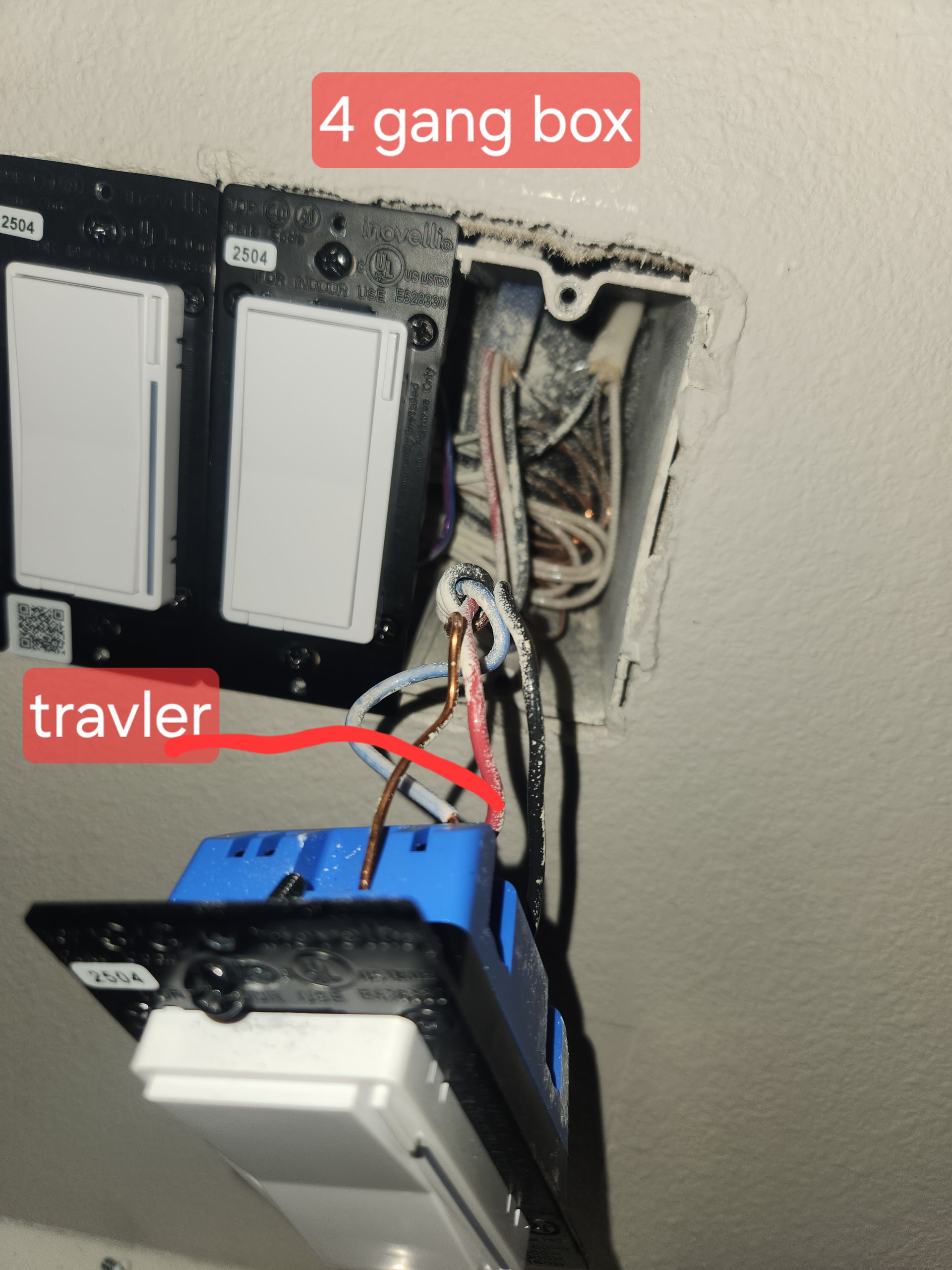
Trying to swap out some switches in my pantry that are wired as a 3-way switch. I’m struggling since I’m not sure if I can use the neutral in the main box. There are two breakers that control the main 4 gang box.
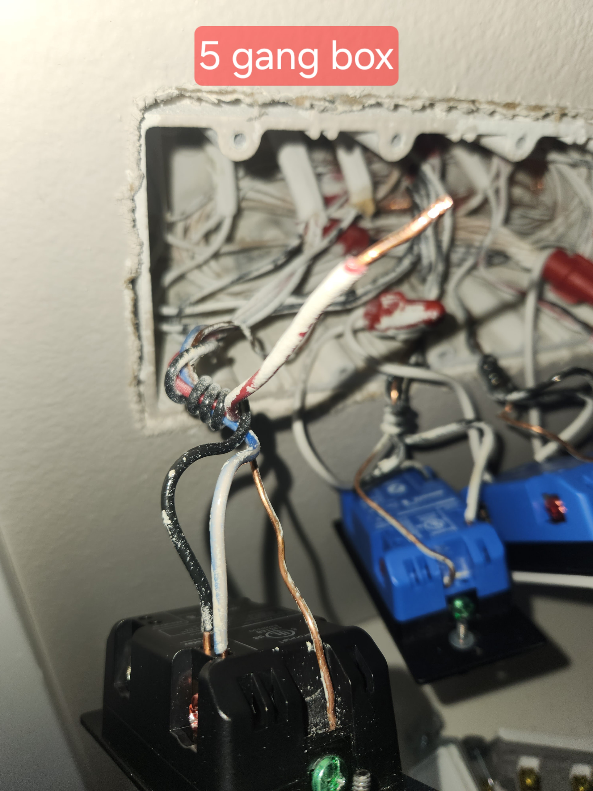
From what I can tell the 4 gang box is where my main load is coming from. I have 2 travelers a blue/white and a red. The black in the 5 gang box seems to be the line. The only way I can get this to work is to wire it up like I have in the picture or swapping the red as the travler and bundling the blue and black wire in the five gang box together. When I do either of these the aux switch does not work at all, but the main switch works and controls the light.
I did not wire a neutral into the main switch. These neutrals in the 4 gang box only have one bundle of neutrals. I’m assuming that since I’m using those neutrals for the other smart switches I shouldn’t use them for this switch since they are on different breaker.
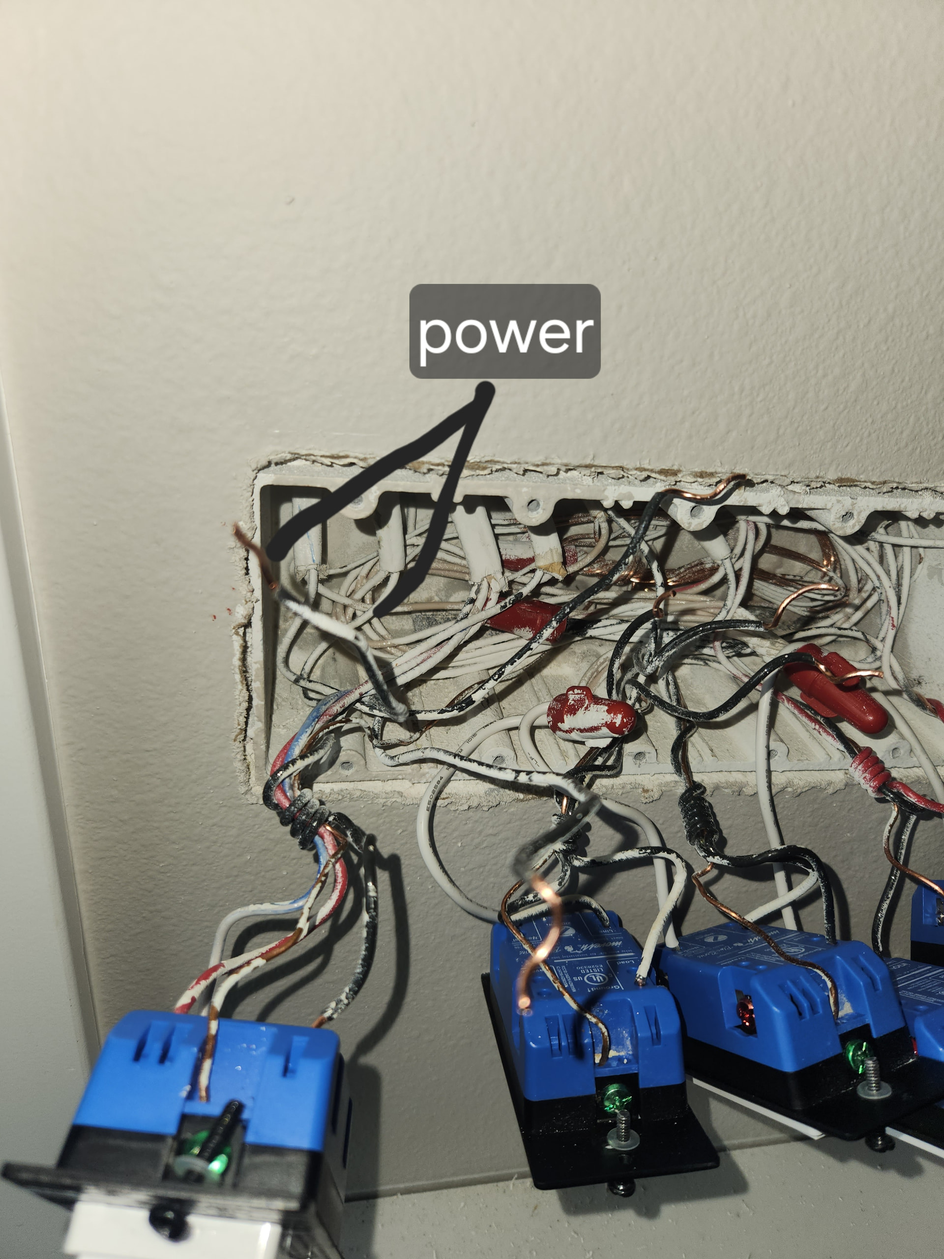
The 4 gang box appears to be a dead end 3-way, so this is where the aux switch would go, and the 5 gang box appears to have both the Line and the Load along with the neutral, so you would install the main switch there.
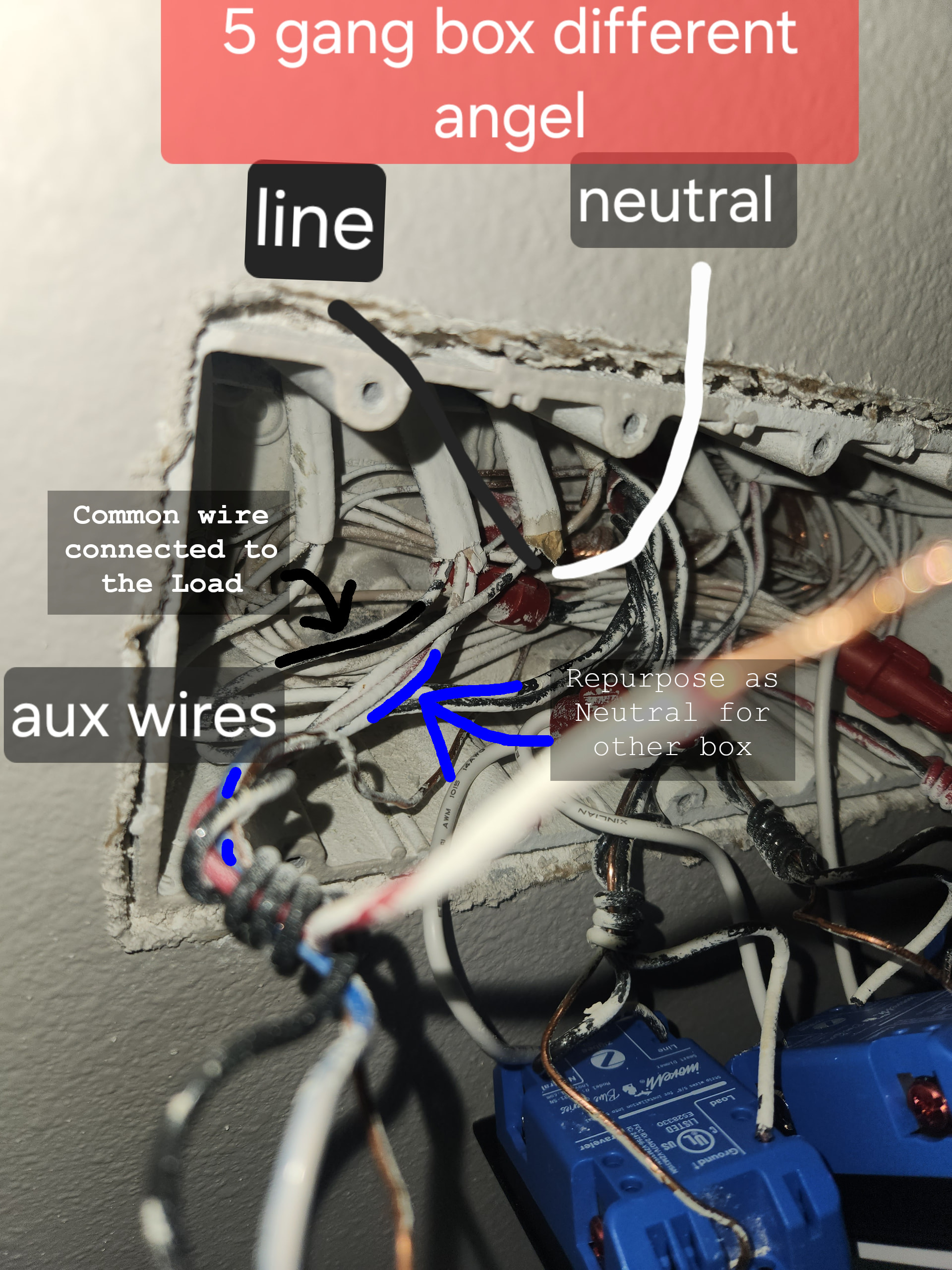
In the first photo, the cable containing the Line you labeled will also have the neutral for that circuit.
.
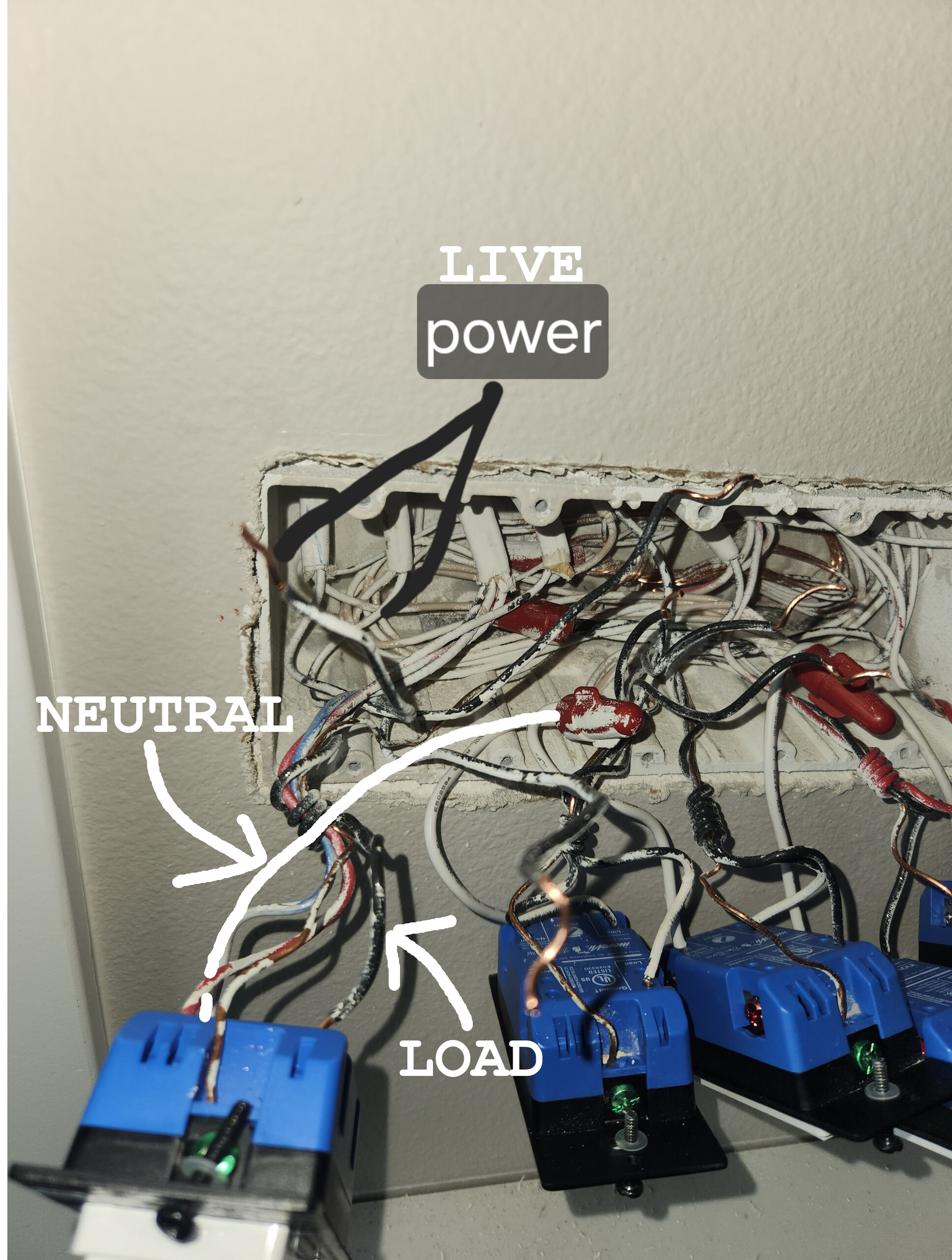
So, in the 5 gang box, you have the Line identified from the 2 wire cable which also has your neutral… the red and blue/white travelers are in a 3 wire cable which also has the common coming back from the 4 gang box. That black common is attached to your Load wire.
You will connect your blue traveler wire in the 5 gang box to the neutrals to carry it to the 4 gang box, and you will use the red traveler as the traveler between the aux and main switch. The black wire going between the 4 and 5 gang box will remain unused and should be capped off.
In the 5 gang box, you will connect the Line, Load, Neutral and Traveler to your main switch.
Actually, seeing as the single black wire you labeled as Line doesn’t go to anything else, make sure that it is actually hot when disconnected and not the Load.
If this is the Load instead, the marked up image I included showing the other black common wire would instead be attached to the Line side of the circuit, and likely to a group of other black wires.
The neutral that cable connects to is still the neutral you will use for these switches though.
@koadic I just checked load as I was reading through your explanation. The wire you indicated does not carry any power. There is one common load which powers all the switches in the 5 gang box. Would I just take a short amount of wire and run it between the bundle where the power is to the switch?
To confirm are you saying to unbundled the white wire and use both the blue and white as neutral? And the blue in the 4 gang box would be my neutral?
For future reference, and for the sake of clarity, as this is feeding power to the switches, this should be referred to as the Line/Live/Hot/Power, not Load, as the Load is the wire going to the light
Provided all of the switches are connected to the same Live, you can grab a Neutral to feed your switch as shown below:
Thanks for the correction. So I can grab a short connecting wire and tie it in with the live bundle and run it to the load? I have a few spare wires from other switches I’ve installed.
For powering the switch, you really want to keep it a black or colored wire… but the included white pigtail is fine for connecting to the existing neutrals.
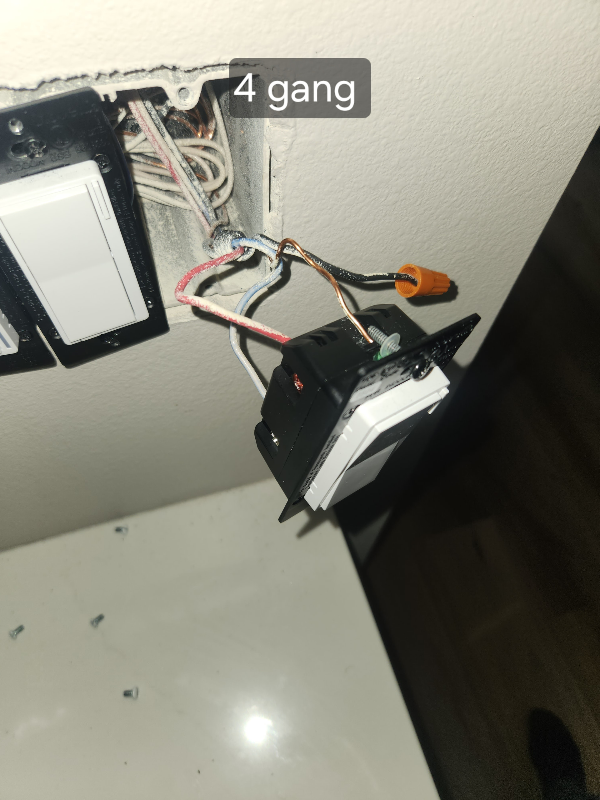
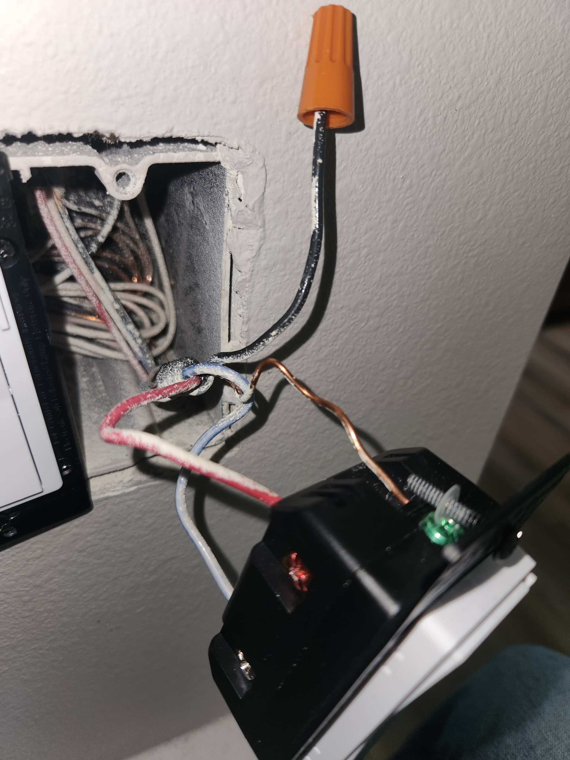
@koadic did I wire the Aux correctly? The main switch controls the light fine, but after programing the switch for aux it doesn’t work. Capped the black like you said, red is travler and used the blue/white for my neutral. Used a black wire for load recommend.
Yes, it looks correct… If the main switch works, and you have the blue connected to the neutral through the main switch along with the red connected to the traveler connection on the main switch, you should be good.
What firmware is the main switch running? Recently, it seems there have been some issues with the timings and settings on some of the Blue and White Dimmers.
While I can’t say that this is your issue, the wiring looks fine.
I’ll try that. I’m sure I have a second aux laying around I havent used yet also to test and eliminate that variable. Thanks again as always! I appreciate you dumbing it down for me and all the help!
Just to be sure, you did add a pigtail from the neutral on the switch to the neutrals in your box, right? and not only the blue/white wire going to the other box, right?
The main switch would likely still work connected in a no neutral configuration if this was the case, but the aux switch would not.