I’ve got five gen2 red dimmer switches. Three of them are deployed successfully as single-switches (two 2/neutral, one without). All are connected to my hubitat and working well.
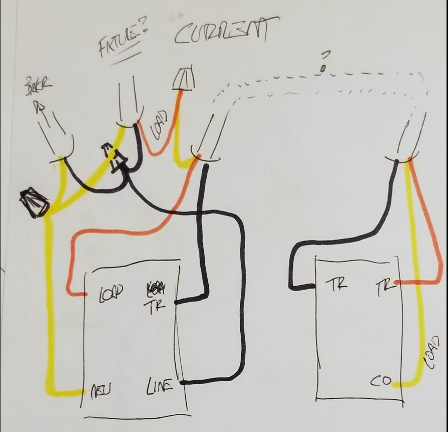
I’m now attempting to connect an LZW31-SN to two ceiling mounted light fixtures (on the same circuit) and dumb switch. The line and load are contained in a gang box where there are 4 other switches as well (including one of the successfully deployed single-switch LZW31’s). See my wiring example below with Inovelli on the left and dumb switch on the right.
The LZW31 is powered and connected to hubitat, configured as having a neutral and 3-way toggle. It’s responding to commands and reporting status.
Problem: The LZW31 works when the dumb switch is toggled up. It will turn the lights on/off and dim them. But if the dumb switch is toggled down, the LZW31 shuts down. status LED’s go out, lights go off, and it won’t respond to local or remote commands. With the dumb switch toggled up, the LZW31 will also sometimes shut-down after a local or remote command to turn off the lights – but not consistently – just sometimes.
When not-functioning, the LZW31 seems to have the right voltages. Neutral/ground are showing zero volts. Hot/line showing 110. But it’s dead. When it stops functioning, I can toggle the dumb switch from down to up and can see the LZW31 restart and function normally again.
To my knowledge the dumb switch is only connected to the LZW31 and the load. I know where the load connection is (and have tied it to a line which is connected to the dumb switch). I also know the hot and neutral lines correctly in the gang box and have probed them.
Since the LZW31 seems to be shutting itself down, I assume it’s seeing a voltage off the dumb switch that it doesn’t like. To double-check the dumb switch romex, I’ve tried disconnecting the LZW31 and the dumb switch, turning-on the breaker, and then probing the dumb switch wires – no voltages on any of them. I’m unclear about why the LXW31 shuts-off – any recommendations?
I’m not intimately familiar with Inovelli dimmers, and you might be right about the Inovelli not liking losing traveler power from the dumb switch, but make sure that you have the constant hot on the line for the Inovelli. In the dumb switch world, that’s a classic indication of the line is not on the common terminal of the primary switch.
As a quick test, check the voltage at the line terminal on the Inovelli with the dumb switch in both positions. Make sure that power to the Inovelli isn’t being cut when you flip the dumb switch.
Thanks Bryan I checked the line voltage when the switch is functioning and when it isn’t. It’s always 110v, and tied to all the other line voltages in the gang including the other LZW31 which is single pole and works OK.
I think its.something “downstream” or associated with the fixture or dumb switch but not clear to me…
The diagram seems to be correct as far as I understand the LZW31 wiring.
The thing that bothers me is you have both line voltage and “dimmed” voltage going to this fixture. You mentioned you have two light fixtures. Perhaps power is coming back from your fixture via the orange wire and feeding into the traveler when is expects to be off.
I would try disconnecting the line from the fixture and try again.
I think the line is coming from the fixture if I understand the diagram correctly. The 2-wire at the top left is going downstream to the remainder of the circuit. So at the light box(es) there is a constant hot not connected to the light, and the lights are connected to the red and the white neutral. So there is dimmable voltage going to the light, but that constant hot black is the incoming line FROM the light(s).
FIRST, I would not power the dimmer again as it’s shutting down the dimmer front plate LED’s and is likely a sign of overloading of some sort. Because no matter where the power is comming from, the Dimmer is getting power regardless of what position the dumb switch is in.
When I “read” the diagram I thought the wires on the left were marked “breaker”.
But it’s irrelevant which black wire the power comes in on as they are connected together.
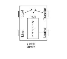
As I understand the LZW series, the “Load” and “Traveler” are alternately powered depending on the state of the main dimmer. I’ve sent an eMail to Inovelli for verification of this.
If that is the case, the diagram should work. Since it doesn’t work the diagram must have an error compared to the actual hardware connections.
I would verify the “dumb” switch is what the diagram thinks (not sure the ? and dotted cable in the diagram:
Turn off power, disconnect the orange and black wires from the dimmer. Measure the resistance of the black to neutral (yellow) with the dumb switch in each position (noting position)
Do the same for the orange to neutral, and see if it matches the diagram. It should be easy as the dumb switch is a simple SPDT switch. The Black screw is the “com” in the below diagram.
Bry & JohnRob. Your comments and fdbk are helpful – thanks for responding. Bry: You are correct in restating how I think the circuits are wired. JohnRob: I agree there’s something wrong here and my assumptions may (must?) be incorrect. BTW the yellow line in the pics is actually the white wire – but used a yellow marker since the paper I used was white. The orange line is actually drawn red but looks orangy in the pics.
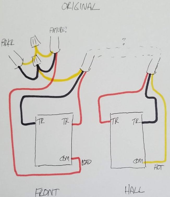
I intend to follow JohnRob’s recommendations to probe/test. In addition, here is the original wiring diagram and some comments about it. I tested the wires in the original config by photographing, marking, and disconnecting them after shutting off the breaker. I turned on the breaker and measured AC voltages compared to ground. At the “front” gang panel switch, all red and black wires were dead. At the remote hall panel the red and black wires were dead and the white wire was hot. I shut down the breaker and tied the red/black/white wires together at the “hall” switch. I turned on the breaker and measured voltages at the front switch. The black wire and red wire connected to travelers on the front switch were hot. The red wire that had been tied to the front switch common and had black tape on it was dead. Based on this I assumed the far right 3-wire romex in the front gang box was somehow tied (directly or indirectly) to the remote Hall switch. To further verify this, I disconnected all the wires at the hall switch that I had previously tied together, and disconnected the white wire from the front that was connected to the other hot wires in the front gang. After that, I re-tested the wires at the Hall switch with the breaker on and all were dead – this led me to the conclusion that the white wire in the front (originally connected to the black/hot wires) was electrically the same as the white wire in the hall.
…which led me to follow the circuit I created and is now not working properly
So I will follow JohRob’s recommendations but pls review my original schematic and the tests I performed and perhaps this will give you further insight into what I performed incorrectly.
@JohnRob I saw the annotation and at first thought breaker as well. But after staring at the diagram for a while, I decided that didn’t make sense.
I’m still confused as to where the power comes in, and I’d like to know the connections at the fixture. Until we know the source of the constant hot and what is going on at the fixture, it’s going to be difficult (at least for me) to get this diagrammed correctly.
Let’s start with the basics. In a properly wired configuration, one of the two travelers at a switch has to be hot, so I don’t understand how you can have power to the hall switch but neither of the travelers are hot. On a dumb switch, the black screw is the common and the two brass screws are the travelers.
So let’s follow your diagram labeled Original, which looks ok to me. Working with dumb switches: I’m assuming that power comes into the circuit from the top left 2-wire labeled breaker. The white neutral goes to the light and the black hot is tied to the black going to the fixture and to the white going to the hall switch. So now we have a neutral at the switch, a black constant hot and a red.
At the hall switch there is a constant hot on the white, which may or may not have a piece of black tape on it. This white wire should connect connect to the black common terminal. So that hall switch sends power over either the black or the red. One of those two has to be hot at any given time, so if that’s not the case, I’m guessing the constant hot isn’t on the common terminal.
So now we have switched power coming into the front switch over either the red or the black. Depending on the switch position, one of those is connected to the common terminal, which has the red wire connected to it. So that red wire on the front switch will toggle hot or not as you toggle the hall switch. If that’s not working as described, you are still miswired.
So now we have switched power coming from the front switch on the red wire. That red wire goes to the light. So at the light, presumably, the red is connected to the bulb supplying the switched power and the white neutral is connected to the other lead. Presumably, the black is not connected and is just powering downstream devices.
Hope this helps. If you can get the dumb switches working properly and diagram accordingly we might be able to help with the Inovelli.
I started to redraw what I though the Inovelli diagram should be. But when I read the below I wasn’t clear about the test you made.
I tested the wires in the original config by photographing, marking, and disconnecting them after shutting off the breaker.
I turned on the breaker and measured AC voltages compared to ground.
At the “front” gang panel switch, all red and black wires were dead. At the remote hall panel the red and black wires were dead and the white wire was hot.
When you said “disconnecting them after shutting off the breaker” did you include the black coming in? If so I don’t have a good idea of what is going on hence the black wire to the com terminal.
I suggest you:
turn off the breaker
In the Front box disconnect all wires going to the Hall box
connect the Hall wires to the “dumb” switch with the black going to the com and the White and Red to the TR’s. Note(1)
With your ohmmeter:
3a) Set the dumb switch to “off” Measure resistance from Black to yellow and black to red. One should be open the other closed.
Set the dumb switch to ON repeat the above measurement. The color pair that was on should be off and the other should be on…
If this works the "dumb’ switch is wired in a way we can use it.
Note (1) you don’t want to feed line voltage through the white any more than you have to.
Lets test the light fixture. It seems the original drawing suggests the fixture has connects to it Neutral (white), Power (black) and switched power (Red). All three of these wires are not needed for the light. Perhaps the original electrician is feeding something else through that fixture. Logic would suggest the lamp is connected to the Red and Neutral (White).
breaker off.
connect the fixture white to breaker white, connect fixture Red to Breaker black.
2a) Do not connect the fixture black
the light should go on and off with the breaker.
With this info we should be able to wire your LZW dimmer.
OK got some time to do some probing. First the dumb switch.
Breaker off.
Disconnected wires from both the inovelli and dumb switch. Unbundled the black wires in the front gang. Kept previously-bundled neutrals still bundled.
Breaker on. Probed wires. All dead at both switches/boxes except the black line from the romex I’ve been calling “fixture.” Surprise! The romex I labeled “breaker” was not supplying power to the bundle…
In main panel, touched hot black wire from “fixture” romex to the red wire (w/black tape) from “fixture” and light went on. Verified this is the load.
Turned breaker off.
Per John’s recommendation, went to the hall panel and attached black to common and red and white lines to travelers. Probed resistance on the front romex bundle wires that I THOUGHT were connected to wires in the hall dumb-switch.
With hall switch in the down switch position, front panel far-right Romex black/red were connected and black/white were not. With switch in the up switch position, front panel far-right Romex black/red were not connected and black white were connected. So the wires in this bundle seem to be the same in each panel (front and hall).
So the only surprise here is the hot black for the entire panel was coming from the “fixture” romex bundle and not the “breaker” romex bundle. But all other assumptions were correct. So I am baffled about why this isn’t working properly. I THINK my circuit is the same one proposed by Inovelli…
Based on the above, I rewired the circuit to reflect a black-wire common at the hall dumb switch – tied at the other end of the black-wire in the front gang to the “fixture” load red-wire. And then connected the red and white wires at the hall to the dumb switch traveler connections – connected at the other end in the front-gang to the load and traveler on the inovelli. Then connected a black/hot wire from the front gang “hot bundle” to the inovelli line. Connected a neutral from the white/neutral bundle to the inovelli.
Switch behaves as before. Functions properly when the dumb switch is up. Shuts down when the dumb switch is down.
When the dumb switch is up and the inovelli is functioning but has the fixture turned off, I see 120v on the line, load, and traveler lines. When I use the inovelli to turn the lights on the line is 120v but both line and traveler lines are 108v. Which suggests they’re heavily loaded. But the two light fixtures only have bulbs consuming approximately 30 watts of power.
When the dumb switch is down and the inovelli stops functioning, the line voltage is 120v, the load voltage is 115v, and the traveler voltage is zero.
…and same voltages at the dumb switch…
So when the dumb switch connects the inovelli load to the the light-fixture load, the switch works.
But when the dumb switch connects the inovelli traveler to the light-fixture load, the switch shuts down.
There are a couple threads in this forum where users are describing the same symptoms where the smart switch only functions with the dumb switch in one position. Makes you wonder if it’s the Inovelli switch that is the issue.
Its difficult to understand how you rewired this time, but the black wire in the Hall should not be the common.
However knowing the power comes from the fixture does not change anything, your first diagram should have worked (good job )
The issue others have complained about appears to be with certain bulbs. If you can find a old incandescent bulb, put it in fixture and see what happens.
If the incandescent bulb works the same as the LED bulbs (I made the assumption your fixture has LED lamps) then your symptoms would seem to indicate one of the outputs of the dimmer are not working. I suspect it might be the “traveler”. To test this connect the dimmer directly to the fixture by connecting the fixture RED to the dimmer “Traveler”. The light should work in one of the two paddle directions (likely off).
If there is no light then you found the issue. If this is the case I apologize for not suggesting you test it earlier.
If the light does not come “on” then connect the fixture red to the dimmer load. It should come on. The reason for this step is that Inovelli will ask you to perform this test when you go back and complain the dimmer doesn’t work. Remember your first diagram is correct, it would not have damaged the dimmer.
Was prepared to do more testing on the dimmer and traveler lines as John suggested. But first replaced all the LED’s in the fixture with incandescent bulbs.
The switches now behave much differently. Here’s what I observed with incandescent bulbs in the fixtures and wiring unchanged from my most recent post (which is electrically the same as the first post – just changed wire colors between the Inovelli and dumb switch):
With the incandescent bulbs dimmed, everything works as before (dumb switch down causes Inovelli to shut-off).
With the Inovelli at max brightness, the dumb switch has no impact. When dumb-switch is pressed from up to down, lights stay at max and inovelli continues to function. – but should have continued to function and turn the lights off).
If I subsequently turn the dumb switch from down-to-up, the inovelli continues to function.
If (instead) I subsequently dim the lights (dumb switch is still down), the inovelli dims them as expected. I can flip the dumb switch up again and lights should go-out but stay dim. If I flip the dumb switch down while Inovelli is still dimmed the Inovelli shuts itself off.
So overall very weird, inconsistent behavior vs when LED bulbs are installed, and still not functioning correctly. Me thinks there is an issue with the Inovelli.
Add’l info: There are 7 bulbs total in the circuit: Two light fixtures. One has 4 bulbs and one has three. The LED bulbs are 4 watts each and rated as dimmable and the same bulbs work correctly with other Inovelli switches I have wired as single pole configs. The incandescent bulbs are 40 watts each.
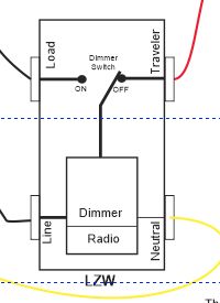
I did not see anywhere here that you set the configuration of the switch. Have you configured it so that it “understands” that there is a dumb switch? This sounds to me like the LZW believe that it is alone in the circuit. The little “wiring insert” tells how to do this manually using the config button on the switch, but if you can connect to a hub like Hubitat, it is much easier to set it via Z-Wave. You want to be sure it is set that it DOES have a neutral (I think the parameter is called “power” in the Hubitat driver) and that it DOES have a dumb-switch attached. Good luck…
following along. I’m having the same issue - LZW only works with dumb switch in one position. I did do the initial programming including setting the neutral and 3 way toggle setting.