I had pre-ordered 10 switches and received them in time for building my new house. I gave them to the electrician along with the instructions and they managed to install all but 2 incorrectly. (They literally had to peel a sticker off of each one that directed them to the directions!)
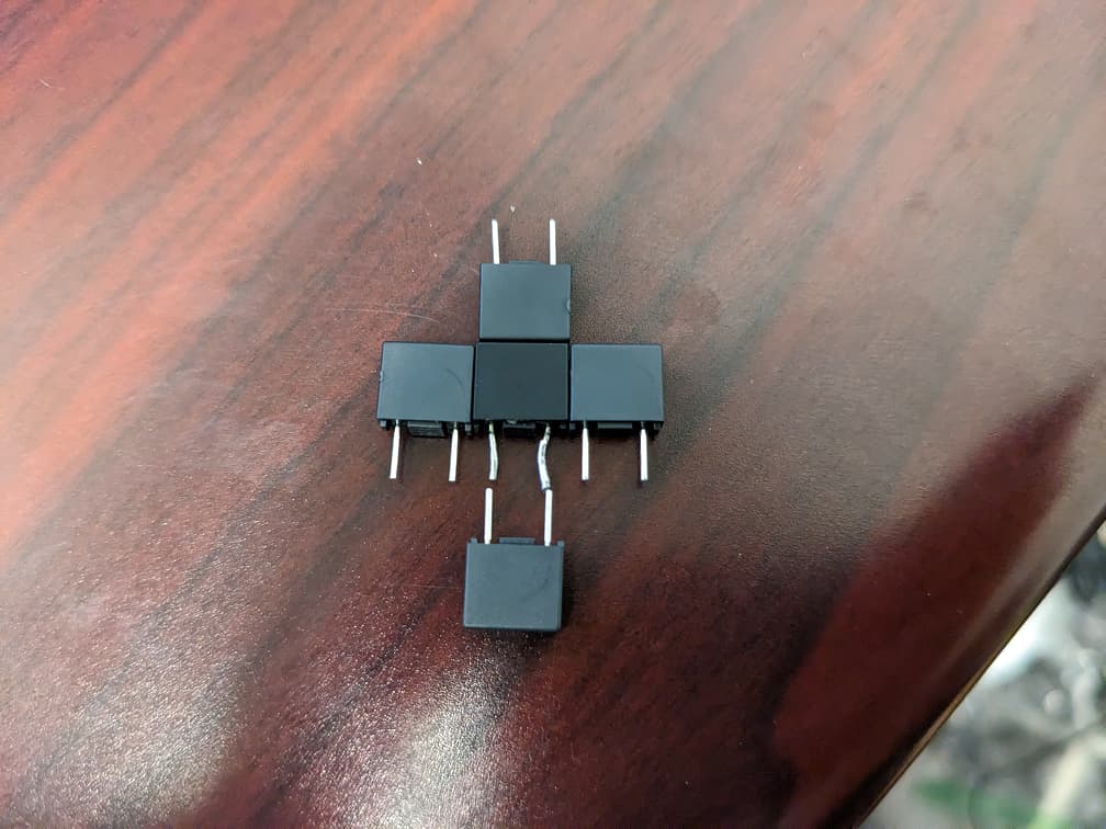
Long story short 2 of the switches were non-functional and one of them seems to not have control of it’s relay. They said they would replace them but I have heard nothing for a few months, so who knows if I will ever get anything. Today I figured I would pull the two completely dead ones apart to see what was wrong. One had a blown fuse (F1), the other had no obvious signs of an issue that I could see. I removed the fuse from the second one and put it in the first (That one now powers up, but even in on/off mode there is no click of the relay, and in dimming mode there is no change in output voltage, it is always just full on). I just went back and looked at the one I robbed the fuse from and one leg of the choke/inductor is not attached at all!
Have others had instances of DOA units or units that are missing functionality like the ability to actuate the relay?
(Also as a side note, are schematics available to help diagnosing these?)
Was there not a manual in the box? The sticker you are referring to is the sticker that covers the traveler screw.
It’s extremely unlikely the unit was shipped with a blown fuse, as they are QC’d before shipping. It sounds as if your electrician wasn’t too familiar with smart switch installation and may have installed improperly.
Depending on the installation topology setting, the relay many not be used, so you may not hear a click. If sounds as if you’re using the dimmer mode, so I woudn’t expect to hear a relay click.
See the manual for Parameter 261’s setting.
Hey @jeffmunk – first, very sorry for the issues – you’re right, I’m not sure how they could’ve messed up that badly when the wiring schematic location is shown directly on the sticker they had to peel off. It’s literally in the first sentence.
I try to make it as, “dummy” proof as possible based on a lot of user feedback over the years, but some people never cease to amaze me.
Anyway, I know our manufacturer does test the relays prior to shipping so while not impossible it could’ve come with a messed up relay, it’s very rare. On top of that, if you’re seeing any smoke marks, I would say that it probably happened during the installation or shortly thereafter.
The biggest culprit I’ve seen is in 3-Way (or multi-way) setups where the incorrect schematic was used or someone screwed up the neutral and line.
In fact, this is the reason there is a sticker on the switch to begin with – we noticed a few years ago when we first launched the Gen 2 Red Series that people were blowing up their switches and it finally came down to the fact that they had Gen 1 switches (either ours or Zooz) installed with a, “dumb” switch on the other end and they simply swapped out their Gen 1 with a Gen 2, but didn’t rewire the, “dumb” switch.
Since different logic was used (with Gen 1’s, we used the neutral wire to detect a change, whereas with Gen 2’s, we used the traveler wires) it caused the fuse to pop. The switch would still work, but you could no longer control the load. Exactly what you are experiencing.
–
Were the switches in question installed in a 3-Way or was it Single Pole? If it was Single Pole, I’m really not sure what could’ve happened.
It’s a shame the electricians aren’t taking responsibility and are ghosting you – let’s see if we can work something out via a PM.
I really don’t blame you guys at all! I know it was the electrician’s fault, and I was not happy with them at all. I am sure the fuse was popped by an improper install. These are very nice switches and I prefer to just fix them to be honest.
There was absolutely a manual in the box. The electricians just decided to not look at it. The sticker covers both screws on that side and has to be removed to install it. (I found several stuck to the wall or on the floor near the switch)
More specifically board schematics if you can. Or at least the model of fuse you used. I found this: Fuse that appears to physically match, but I would like to be able to compare electrical characteristics or order the original.
As an update, I installed one of the units that would not actuate the relay and it was still acting wonky. I included it in the network anyway and from home assistant I was able to see that it was in smart bulb mode. I switched to normal and that switch is working now. I now have 2 of the 3 I was having trouble back up, I just need to replace the fuse in this last one and we should be good to go.
One other thing, it one of the paddles looks like they went at it with a screwdriver or something, I was going to order another one, but it looks like they are out of stock, what is the difference between the 2 in 1 and the dimmer switch paddles?
(Also as a side note, I have found that every time you make something idiot proof they make a better idiot)
In your limited case, so long as you are ONLY swapping out the paddle and NOT the airgap, then the Red paddle will work (accoring to Inovelli) on the Blue. It is the airgap pieces that are different between the two switches.
Did you not get any bad Blues on the first go-around? If so, grab one of those.
![]()
![]()
![]()
Have you actually tried that? I tried it a several months ago and if I recall correctly, you cant just swap the airgaps. The different size airgaps have different size tabs on the paddle. I think I could ‘force’ it in, but didn’t really work properly IIRC.
And I don’t think Inovelli ever said the airgap was swappable between Red and Blue. They said the airgap is different. I’m pretty sure the whole paddle/air-gap assemble needs to be swapped out together.
No, but I checked with the horse’s mouth before posting. Hopefully the horse won’t turn out to be a jackass, lol.
BTW, the OP just wants to swap the paddle, not the airgap. He is going to use his existing airgap.
What I’m saying is the spot in the paddle where the airgap goes is a different height to accommodate the different length airgap lever. Both the paddle and the airgap are different. Like I said, I think i was able to force it in, but it didn’t really work smoothly
Some seem to have success.
you can use the original dimmer plates they sell (Which I have done and posted about), you just cant use the air gap, as they is slightly different, but I have posted the stl for the air gap. Let me find it
Found it:
Also here is the link to my post about it:
I think that is if you use his stl file to 3d print a compatible airgap as stated here…
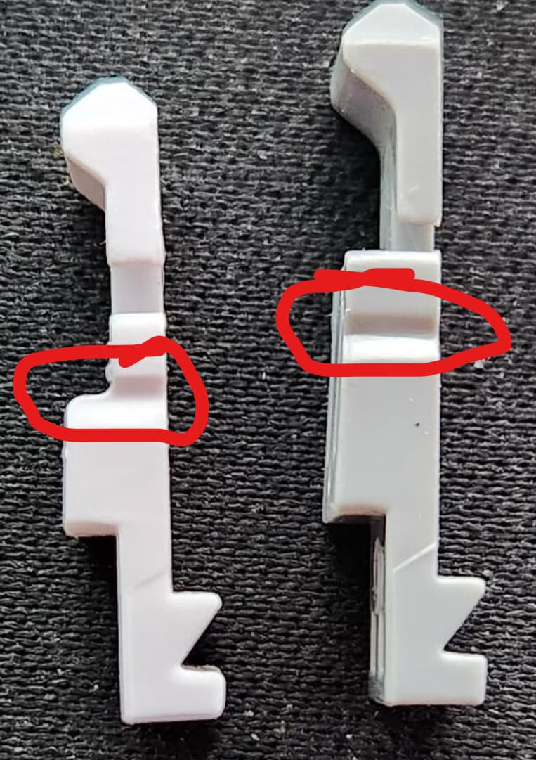
Here is his pic of the two different airgaps. Notice the notch is in a different place and that notch aligns with tabs on the paddle housing. Its close, but different. Anyone is free to try it and might be ok with it, but it is NOT the same and jammed up in my testing. YMMV
I have purchase like 15 of the gray and black dimmer plates for the red series and just swapped the airgap and it works 100% without issue on the blue 2in1 series. and i can pull the airgap easily.
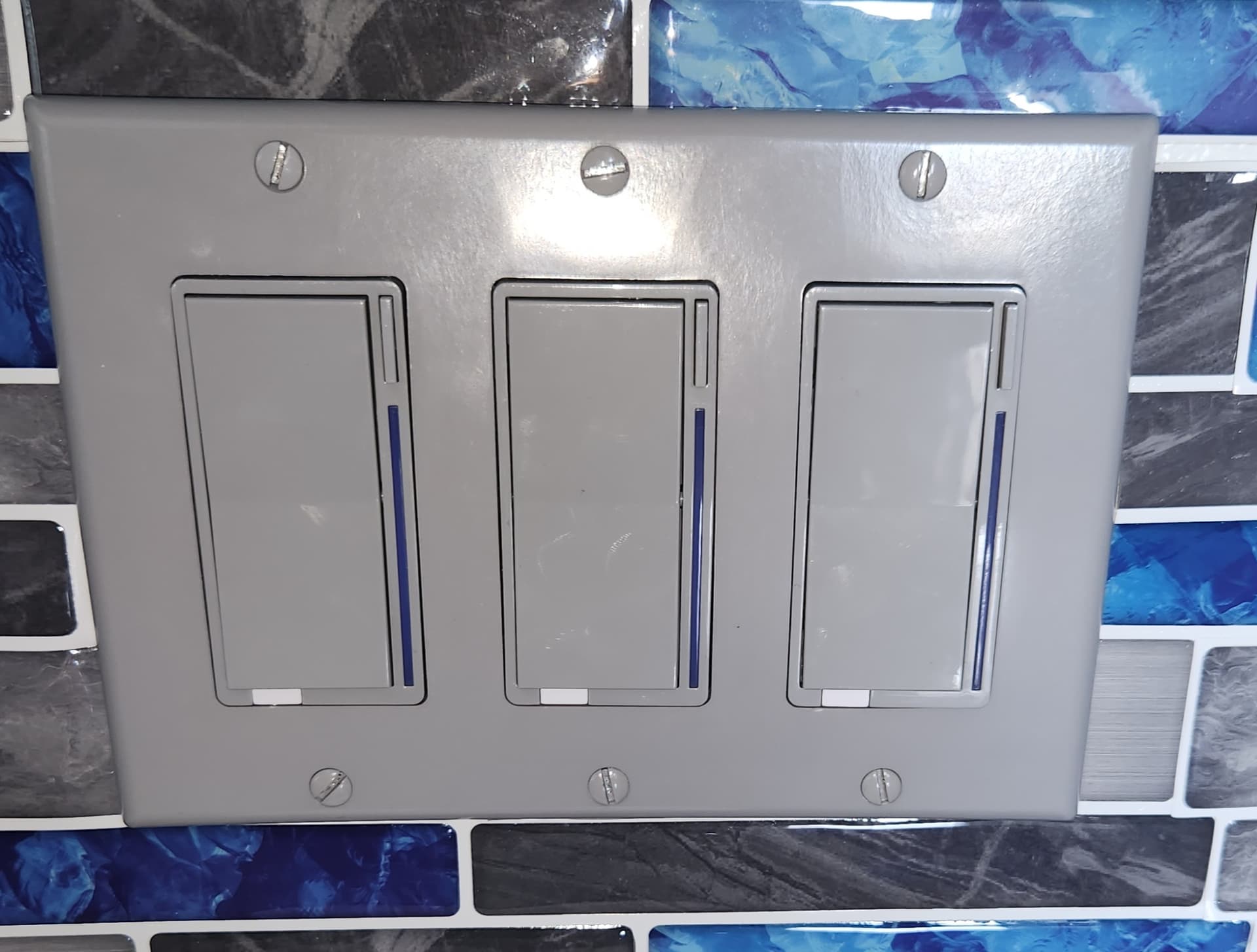
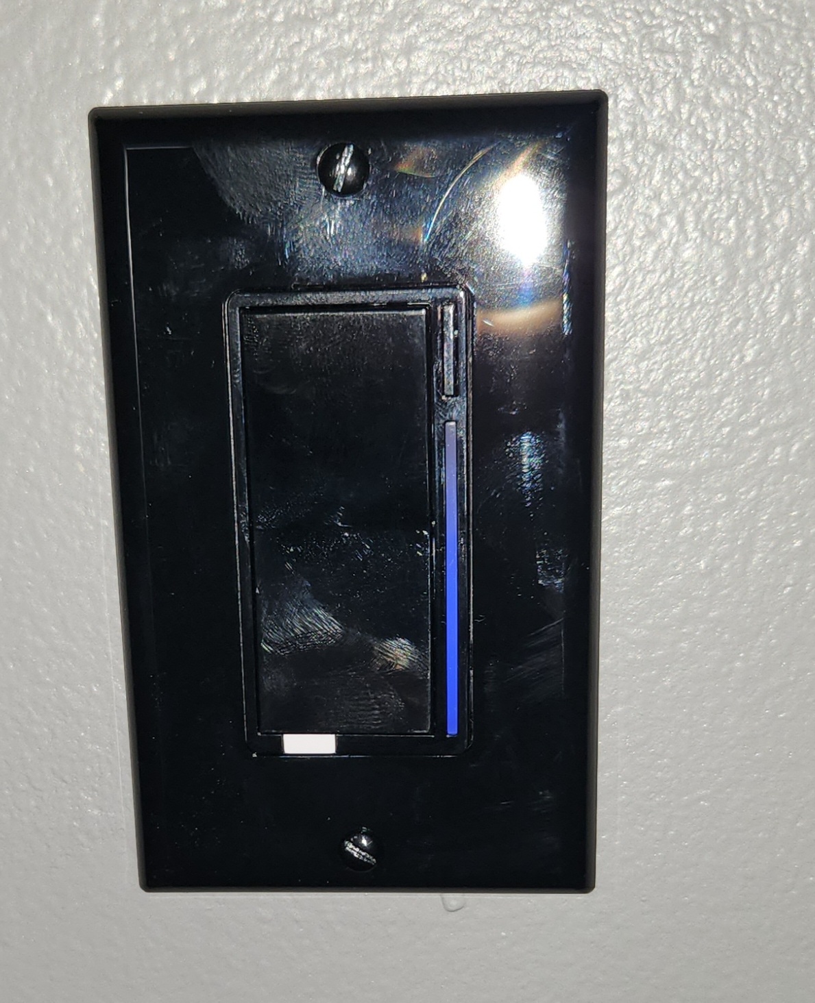
Here are 2 pics showing the blue series switchs using the red series plates and the blue series air gap.
3d printer needs repairs so i have not 3d printed mine yet. But might just use paint to change it from white to gray/black
Give me a few and i will post a guide to make it work
That’s good to know. But clearly there is a difference in where that notch is. How are you aligning the Blue notch with the Red tab? I suspect it’s not. So maybe not quite 100% without issue ![]()
My testing was done on pre-production test units so maybe the tooling has changed a bit since then. ![]()
Yes there is a slight difference, it just pushes the tabs on the red series outward slightly. but once installed it stays in, and comes out without issue and goes in without issue.
Posting a video showing how I did it and how it functions. no issue with the airgap popping out or not going in.
Forgive my video recoding as I was using my phone and looking at screen while doing the vidoe

Great video. I wasn’t taking the paddle off the frame and was inserting the airgap before re-installing the whole assembly. That’s very likely why I was getting jammed up. Your procedure looks like a much better method. ![]()
Hi, did replacing the fuse work? Also how did you get the switch apart to desolder - was it the tiny allen screws?
Just had a short in a ceiling light blow the fuse on my Blue.